Category Archives: electronics

A Design for a Remotely Readable Fuel Oil Tank Gauge

Last summer when I unpacked my electronics hardware (after 25 years) and began to learn about the Arduino microcontroller, I started on a project that would help be pick up where I had left off. I chose to tackle the problem of remotely reading the level in our residential fuel oil tank.

In Atlantic Canada, residential heating is limited to electricity and fuel oil. Our tank is in the garage, in the far corner from the household access door on the lowest level of our four-level backsplit home. In other words, it’s an inconvenience to determine the level of oil in the tank. This might be a non-issue except for the fact that we are not on a more expensive fuel plan where the company regularly tops off the level. If I don’t keep an eye on it, we’ll run dry. It hasn’t happened–yet.

I did some initial research to get a sense of what was already out there. Google Patents had many filings that were interesting, such as “Residential fuel tank oil level” “Remotely readable fuel tank indicator system” and “Hall-cell liquid level detector“.

One design limitation that I had imposed from the beginning was that I did not want to change anything on the tank itself. The level detector had to be completely passive and unconnected in any way from the tank itself. My reasons were twofold:

  1. I did not want to change the status of my house insurance by affixing a non-standard item to the oil tank
  2. I wanted to be able to easily disconnect the hardware from the oil tank for maintenance of the unit

The above-mentioned patents were interesting to me because they used hall-effect sensors. Used as proximity switches, these devices can detect the change of a magnetic field without being mechanically coupled to the item being sensed. They are very inexpensive and solid state, so they are very dependable and have a practically infinite service life.

There is a commercial product available which already does some of what I was looking for. Syba Systems in Connecticut markets several devices such as the “LED at a Glance” which fits over top of the mechanical tank level guage and shows the level using an array of LEDs. “Oil Alert” is similar except that when a low oil level is detected, the unit beeps.

One last example of ‘prior art’ is Tom Laureanno’s “Oil Level Indicator Project/Idea” where he describes placing a magnet on top of the mechanical level, and effecting a change of state of a reed switch.
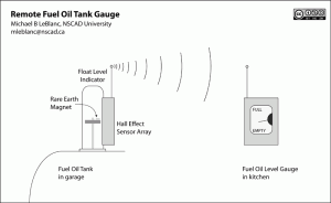
The Remote Oil Fuel Level Gauge

Reed switches are mechanical devices, and they tend to be rather large. Rather than actuate just one switch (resulting in an ‘idiot light‘ scenario, I want to get a sense of the level in several stages, which means that I would need several sensors along the length of the float level. I would be able to watch over time the level go down as we use the oil in the tank.

So this is my idea: To build an array of hall-effect sensors and affix them to the outside of the mechanical float level.

  1. On the float level, a small rare-earth magnet is glued to the float indicator.
  2. As the float indicator rises or falls, the magnet field changes are sensed by the hall-effect sensors.
  3. These sensors are read and interpreted by the Arduino, which transmits the float level information by radio to a receiver elsewhere in the house.
  4. The received information is decoded and another Arduino microcontroller drives an indicator, which in the case of my first prototype, a stepper motor, but it could also be an LED array or an LCD display.

In subsequent posts I’ll outline the design and implementation of the system.


Creative Commons License
Remote Fuel Oil Tank Gauge by Michael B LeBlanc is licensed under a Creative Commons Attribution-Noncommercial-Share Alike 2.5 Canada License.
Contact the writer for permissions beyond the scope of this license.


Seeed Studio Visit – Shenzhen, China

(Wuhan, China) On Monday I visited Seeed Studio, a small but growing tech startup in Shenzhen. They specialize in open source hardware, and are known for the Seeeduino, an Arduino microcontroller board. Seeed makes open source “brick” addons that allow sensor and actuator connections to the Seeeduino without soldering and they provide economical starter kits that are perfect for our students at NSCAD University.

They generously provided me with a sample Seeduino, and two kits: the “Electronic Brick Starter Pack” and the “Catalyst” kit that they have prepared for Make magazine for my lecture at Shenzhen Polytechnic that afternoon. I’ve used their bricks before and find them very convenient for learning how to use the various sensors, motors, LEDs and other actuators, though I have to admit that I broke a light sensor early on when I plugged it into the brick the wrong way around. Apart from that silly mistake, the brick system is robust and well-designed.

Two of the principals, young engineers Eric and Fan, were my hosts. They showed me a beta version of their soon-to-be-released DSO nano, a small handheld digital storage oscilloscope for people like me. It looks like an iPod Touch, but with a button rose at the right. They tell me that they would like to use a complete ‘glass interface’ like the iPod with their next version of the product.

Eric brought out a development prototype of their Rainbowduino called the 3D RGB Cube, a 3D matrix of RGB LEDs that connect smartly to the Seeeduino. With this system there are no worries about current requirements, all you need to do is plug it into the microcontroller and ensure that you give it enough juice.

Now, off to Beijing!

Interfacing Arduino with SMCC-547 Stepper Motor Controller

This week I received a package from my favourite electronic component supplier Futurlec. It contained a very inexpensive stepper motor controller unit called an SMCC-547, made by a company in Thailand. The motor is small, has very little torque, and it has 18° steps, which is quite coarse as stepper motors go. Since I have no experience with stepper motors, I bought it thinking that I would be able to wire it up quickly to an Arduino microcontroller and play with it using Arduino’s Stepper Library.

Unfortunately, the library does not work for this controller. I have not found anything online that shows how to connect this to an Arduino, so I’m documenting it here, as much a reminder for me in case I want to go back to it, as for anyone else who can use it.

Tom Igoe’s stepper motor circuits page shows most motors as requiring a certain sequence of pulses on the four control wires of the motor:

Step wire 1 wire 2 wire 3 wire 4
1 High low high low
2 low high high low
3 low high low high
4 high low low high

However, all this does on the SMCC-547 is make the motor wiggle nervously.

By successively bringing each input HIGH I was able to learn that the correct logic for this controller is to bring the ABCD inputs high in order to make the motor rotate clockwise: A-B-C-D, and to make the motor rotate clockwise, do the inverse: D-C-B-A.

This required writing an Arduino sketch (program) from nothing, but after an hour or so I had this demonstration circuit running. A light sensor is connected to analog pin 0 on the Arduino. In the demonstration sketch, if there is lots of light on the sensor, the motor turns clockwise, and if the sensor is shaded, the motor turns counterclockwise. The sketch is shown below:

/*
Stepper Motor Demonstration
for SMCC-547 Stepper Module

by Michael LeBlanc
NSCAD University
mleblanc@nscad.ca

It checks analogPin(0) and if it is higher than 512,
it rotates the motor clockwise, otherwise counterclockwise.

August 27, 2009
*/

/*
**************** N O T E **************************************
This unit does not work with the stepper.h library.
It works by setting one pin high and the others low.
To rotate clockwise, set inputs high in order A-B-C-D,
and D-C-B-A rotates counterclockwise.
***************************************************************
*/

int analogPin = 0;
int activePin = 1;
int outputPin[5] = {0,10,11,12,13};

void setup()
{
pinMode(10, OUTPUT);
pinMode(11, OUTPUT);
pinMode(12, OUTPUT);
pinMode(13, OUTPUT);
Serial.begin(9600);
}

void rotateLeft()  // rotate counterclockwise routine
{
if (activePin == 4)
{
activePin = 1;
digitalWrite(outputPin[4], LOW);
digitalWrite(outputPin[1], HIGH);
}
else
{
digitalWrite(outputPin[activePin], LOW);
activePin = activePin + 1;
digitalWrite(outputPin[activePin], HIGH);
}
}

void rotateRight()   // rotate clockwise routine
{

if (activePin == 1)
{
activePin = 4;
digitalWrite(outputPin[1], LOW);
digitalWrite(outputPin[4], HIGH);
}
else
{
digitalWrite(outputPin[activePin], LOW);
activePin = activePin - 1;
digitalWrite(outputPin[activePin], HIGH);
}
}

void loop()
{
int v;
v = analogRead(analogPin);
//Serial.println(activePin);  // for debugging
if (v > 512) //choose any number between 0 and 1023
{
rotateRight();
}
else
{
rotateLeft();
}
delay(200); // this sets the speed of the motor
}

This sketch is somewhat “brute force,” but it works. A much more elegant solution would be to populate the array with 4-bit binary values and use bitwise shifting and boolean ANDing to assign each output pin of the Arduino a HIGH or LOW state; I found an example of this technique in the Arduino Playground.

Creative Commons License
Stepper Motor Demonstration for SMCC-547 Stepper Module by Michael B LeBlanc is licensed under a Creative Commons Attribution-Noncommercial 2.5 Canada License.