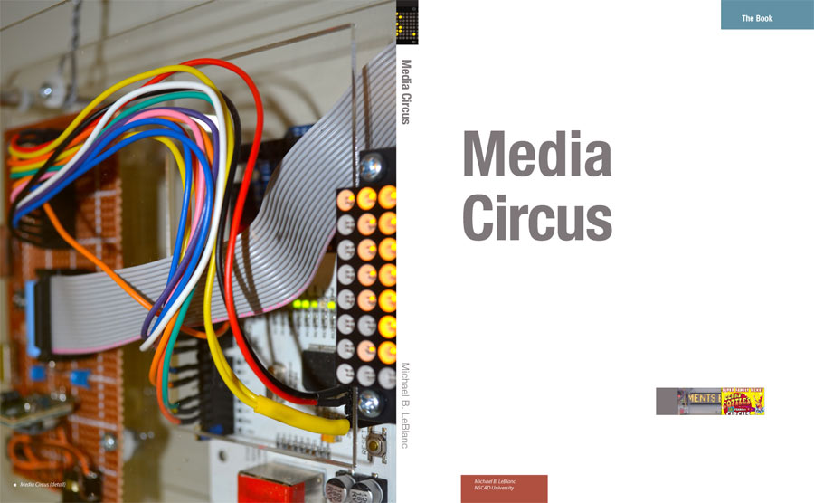
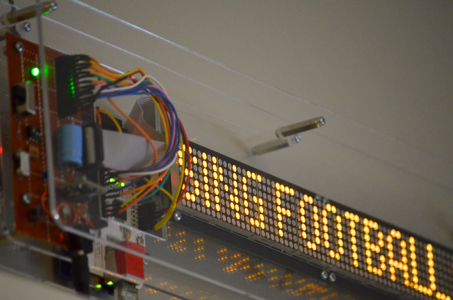
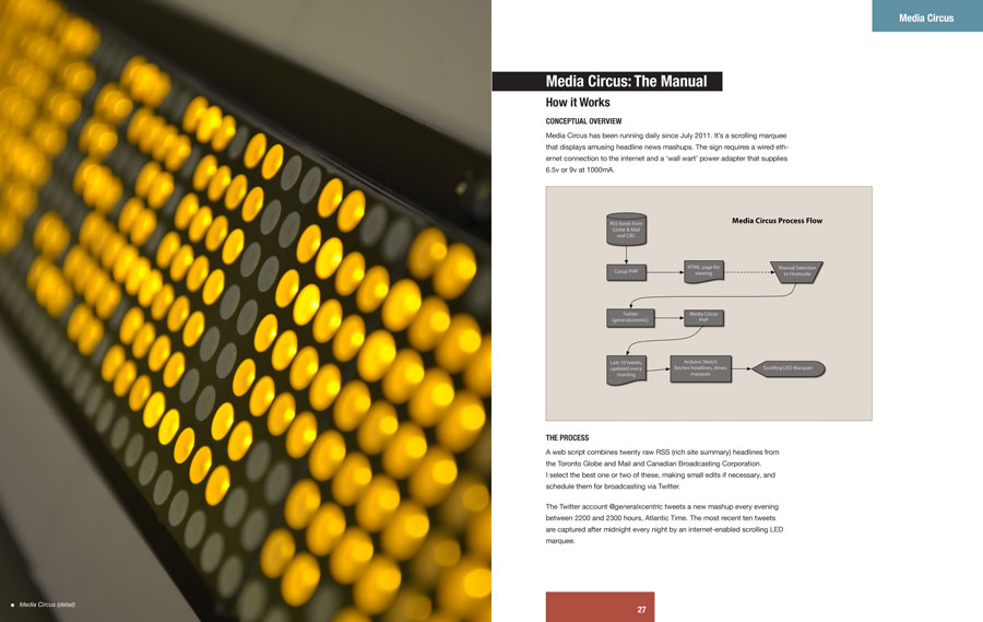
Media Circus is an electronic, internet-enabled scrolling marquee that displays amusing news headlines. Media Circus uses @generalxcentric’s daily tweets, which are cutups of contemporary news headlines from the CBC and the Toronto Globe and Mail.
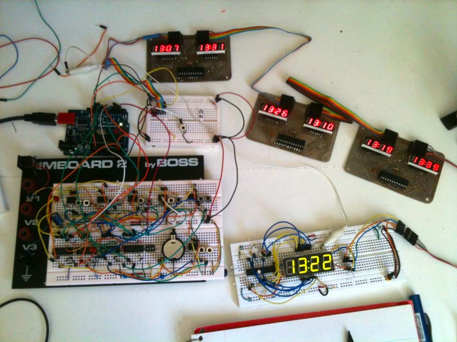
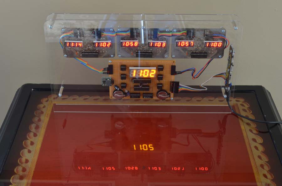
Average Clock is six clocks running independently, slowly diverging, while a microcontroller tries to make sense of it all.
The quartz crystals that regulate most household clocks oscillate at 32,768 cycles per second. This frequency is used because it is equal to 2^15 cycles per second, and hence can be divided easily by computers using base 2 math. In practice, however, inexpensive crystals never run exactly at 32,768 cps. The discrepancy shows up over days or weeks and we have to adjust the time—from time to time. Crystals are also affected by temperature, aging, shock and even radiation.
Average Clock was developed on the premise that consumer-grade timekeeping crystals diverge in accuracy equally above and below the target frequency. Given enough inaccurate clocks, if they are inaccurate equally, the average time will be correct.
This appliance depends on failure for its accuracy… That’s the theory, anyway.
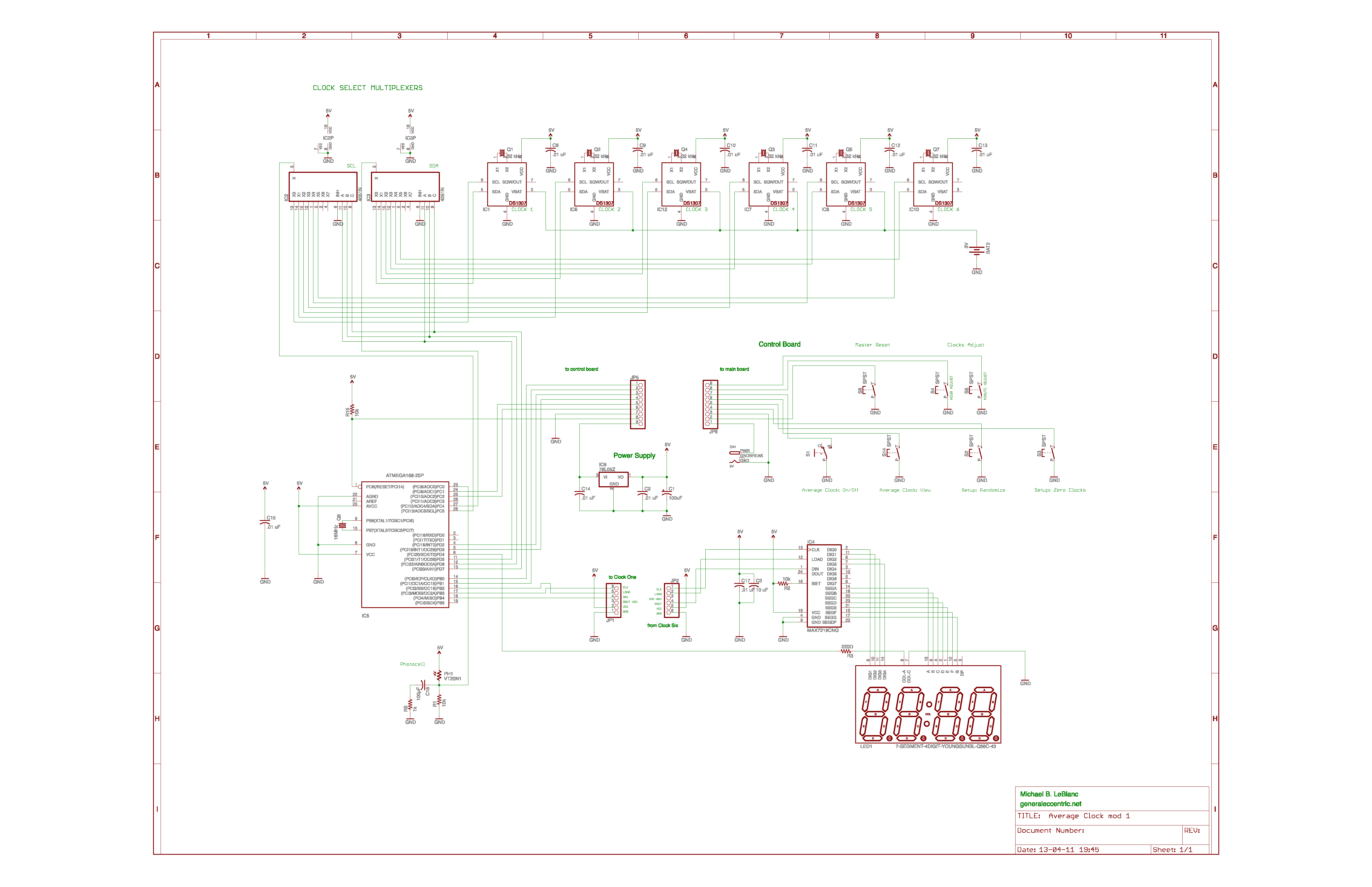
The six clocks are Maxim DS1307 real-time clock chips. They require a minimum of additional support circuitry: VCC and Ground, a 32 kHz crystal, a couple of 4.7k resistors (which are not required because we’re using pullup resistors in the controller) and a 3v backup battery. The chip communicates with an ATMEGA328 using the I2C protocol, using just two wires: SDA (serial data input/output) and SCL (serial clock). These lines are connected to the controller on Analog pins 4 and 5.
The I2C protocol has a wide address space, which basically means that you can—in principle—hang a hundred different I2C slave devices off of just two wires, and as long as you know the address of each device you can read or write to it. Most I2C devices, such as memory, LCD displays and bus controllers are individually addressable, but since Maxim figured that only someone truly demented would want to have more than one clock in a device, they designed the address of the chip to be the same for each chip.
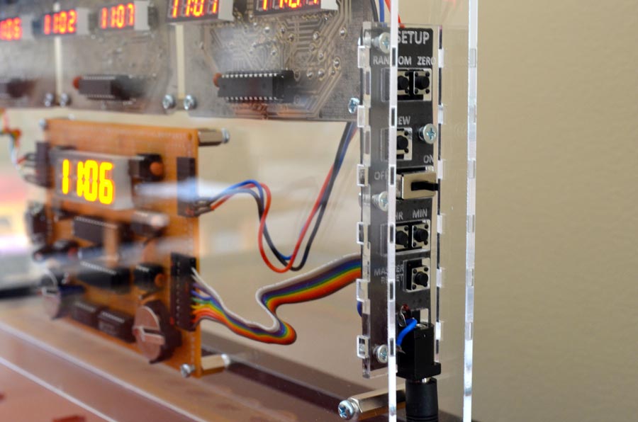
Average Clock Control Buttons
This drawback is solved with external hardware, using two 4051 CMOS multiplexer/demulitplexer chips. The 4051 allows us to direct our attention to one of up to eight—though we only need six—of the clocks. We need two 4051’s: one for the SDA line and another for the SCK line.
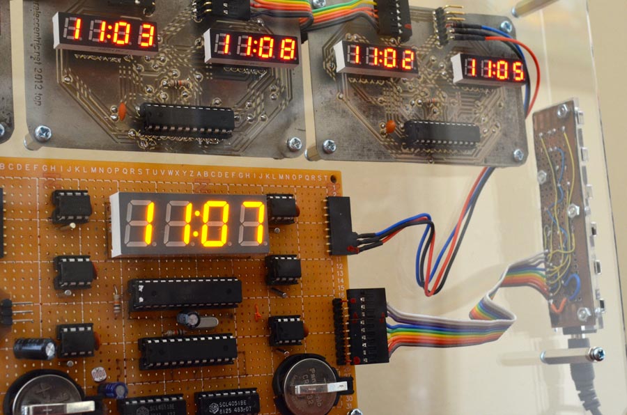
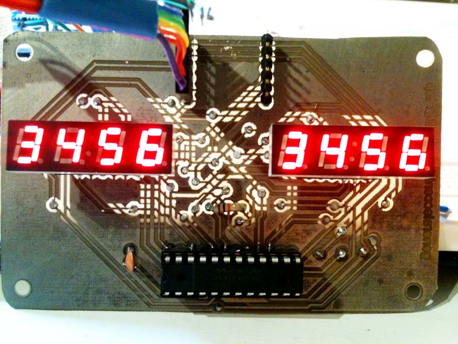
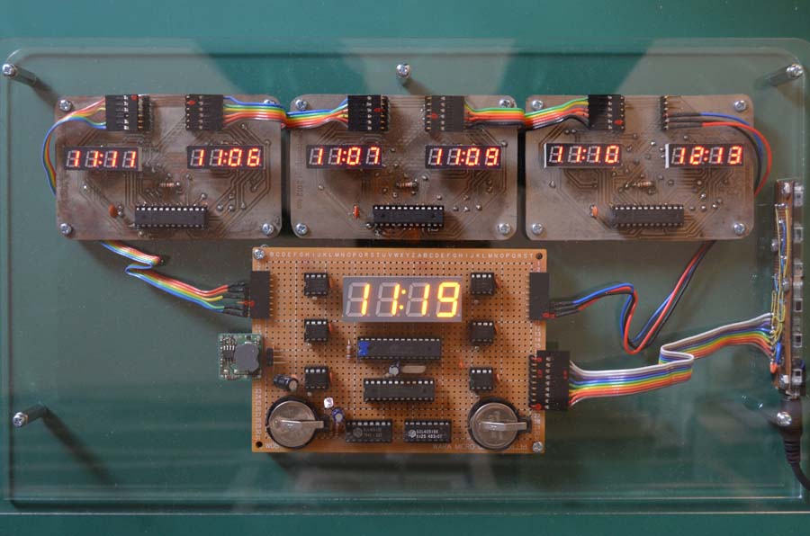
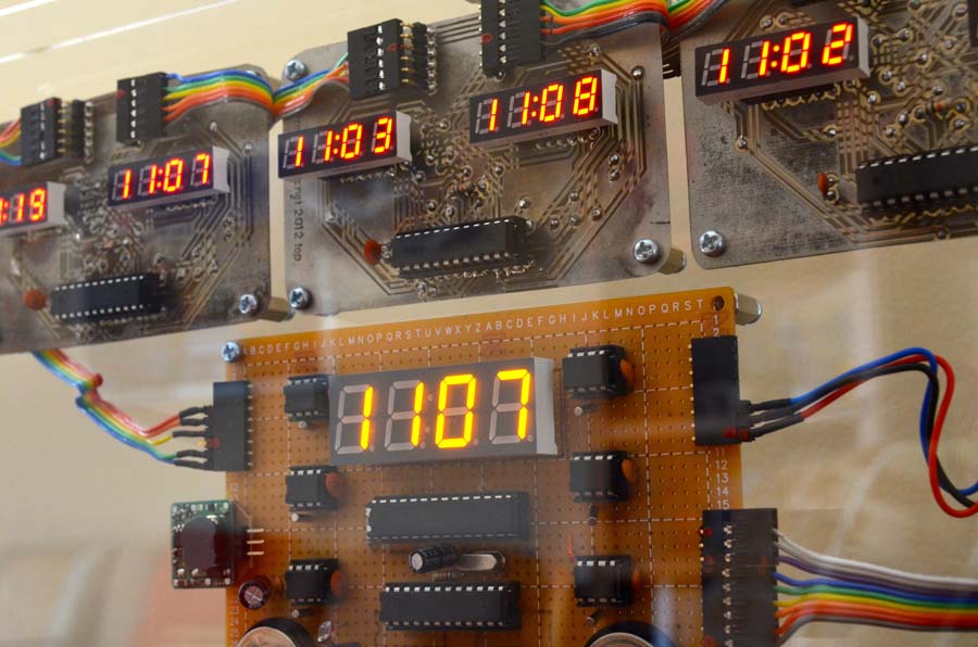
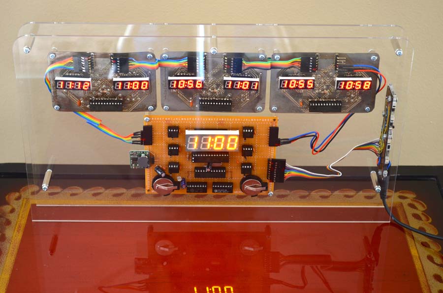
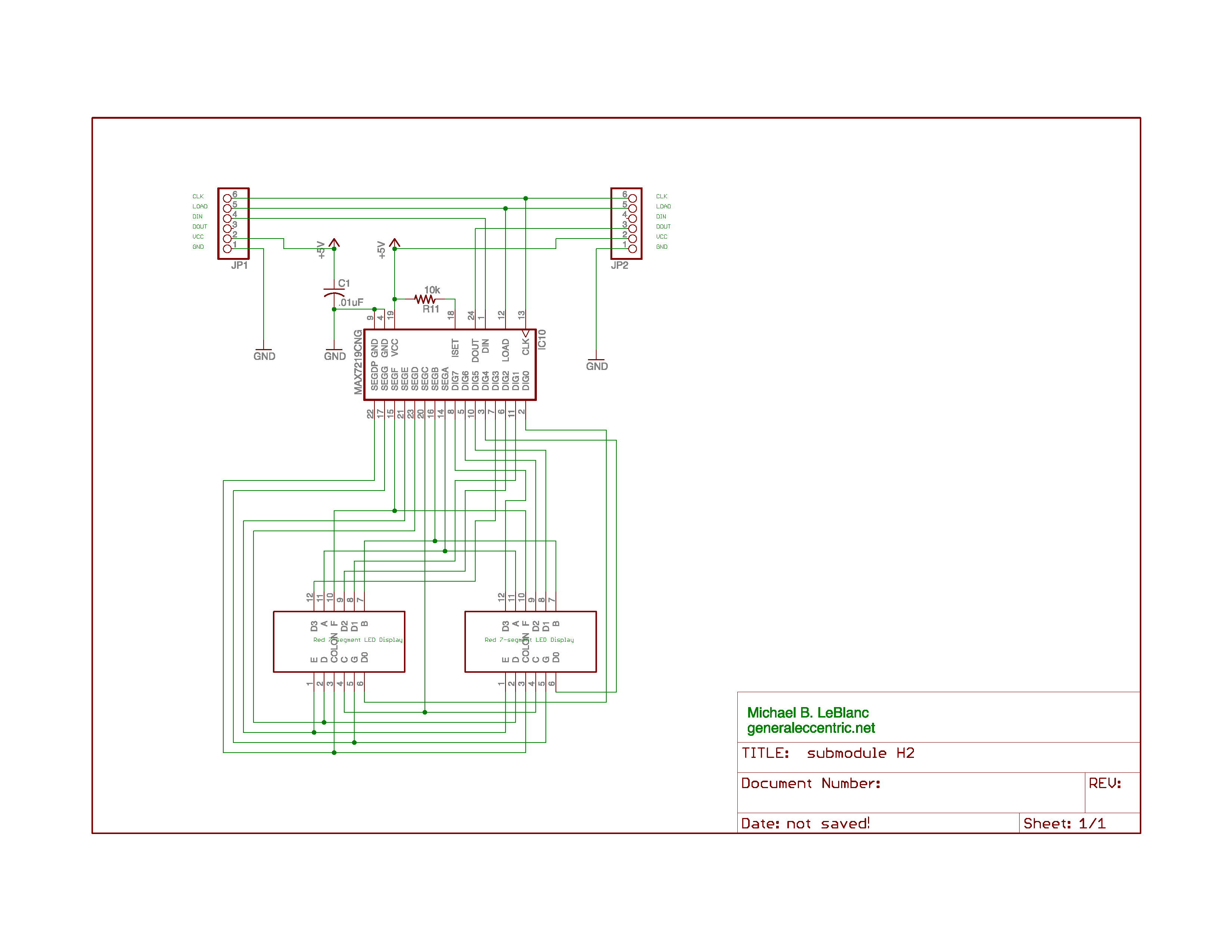
Time for each individual clock is shown using small red seven-segment 4-digit LED displays. Three MAX7219 LED driver chips display the six times and a third 7219 displays the average time using a larger amber 4-digit display.
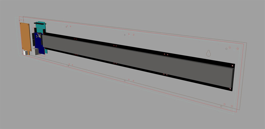
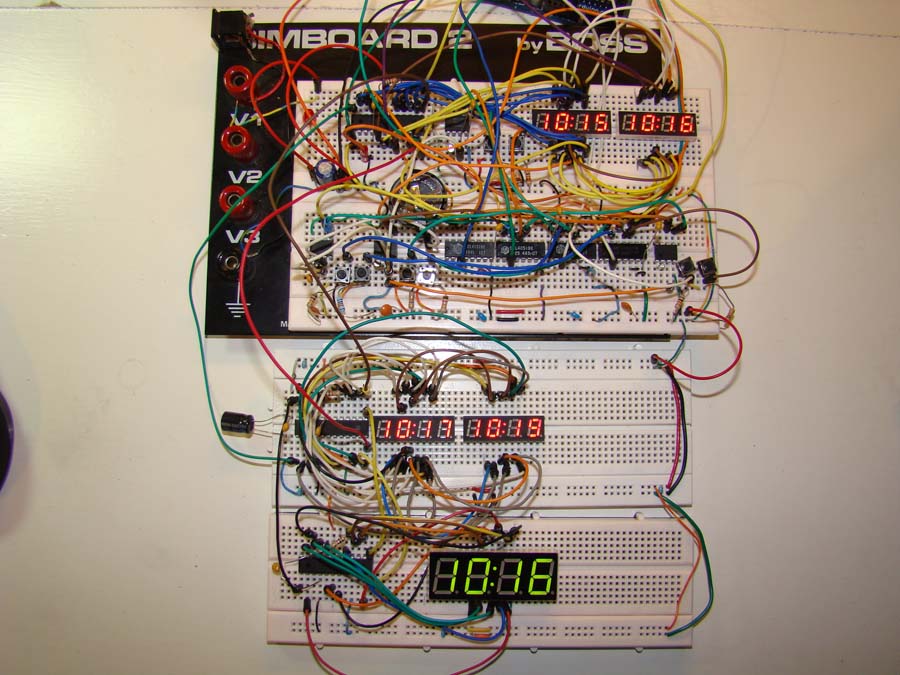
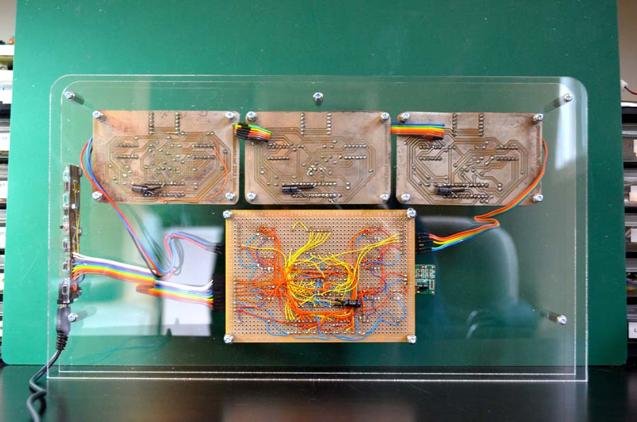
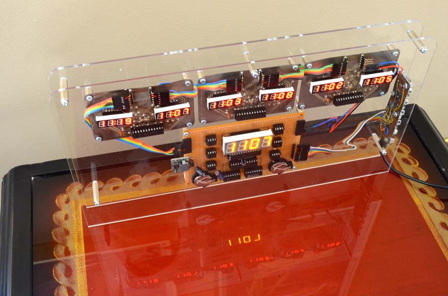
The circuitry is modular: three display modules on a home-made two-sided printed circuit board are connected to a hand-wired main microcontroller interface that holds the clocks, batteries and microcontroller.
Average Clock has a small control panel oriented at right angles to the rest of the hardware.
The software handles the clock initialization, multiplexer control for addressing each clock, sending the clock data to the MAX7219 LED drivers, and calculating the average time. This was, in some respects, the most challenging part of the project. While it’s fairly simple to sum each time reading from six clocks, then divide that by 6, I discovered the “day rollover problem”. When approaching 23:59, the average time became erratic as each clock rolled over from 23:59 to 0:00. I experimented with various methods of overcoming this problem but as the program became more and more convoluted, I decided to give up, or at least put the problem aside for a rainy day. I can always pull the controller chip and re-flash it if I come up with a solution later.
Control
MASTER RESET activates the reset pin on the controller, causing it to reboot.
Average time can be hidden with the View switch; when it is in the VIEW OFF position,
pressing the VIEW button turns on the average time. When the switch is in the VIEW ON
position, average time displays normally.
Setup Procedure:
Press the ZERO button. This sets all clocks to 0:00.
Using the HOUR and MINUTE buttons, set all clocks to the correct time.
Press the RANDOM button. This changes each clock by +/- 5 minutes. Press several times to scramble each clock while keeping the average value the same. Be prepared to go back to Step 1, since the clock scrambling may move the average clock time ahead or behind, and the more you randomize, the worse it gets. Ideally, two or three RANDOM presses should result in a correct time reading on the Average Clock.
You may disconnect the power at any time; the two CR2025 lithium cells will keep the clocks running at extremely low currents for months, or possibly even years. If you need to replace the batteries, you should disconnect the main power first.
I’ve included an automatic adjustment for LED intensity based on ambient lighting. No extra charge.
Some times the displays will lock up: press MASTER RESET to return the clocks to normal.
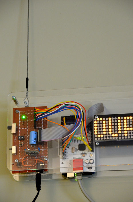
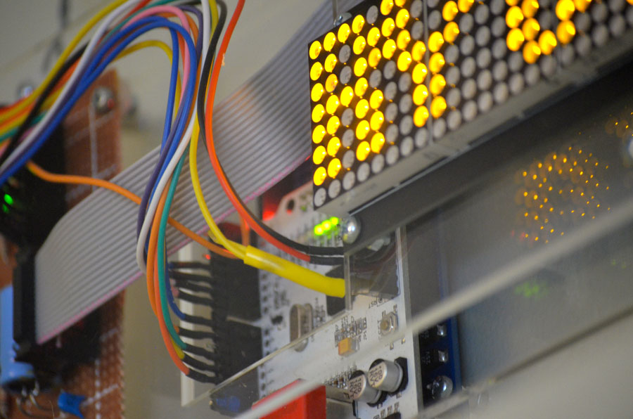
The SURE module is an LED matrix with a LED matrix controller built-in. A hand-wired board featuring an ATMEGA328 microcontroller, a DS-1307 battery chip with a button clock backup, and a 5v high-efficiency regulator drives the SURE module.
The JY-MCU 3208 also has the same matrix controller, but also includes an ATMEGA8 controller; no extra wiring is required except for a light sensor attached to a spare data input pin on the ATMEGA.
The JY-MCU 3208 currently sells for just over $12 at DealExtreme.com. It arrives with software that displays date and time using Chinese characters. Fortunately, the module includes a standard six-pin ISP connector that allows hobbyists to upload their own code using AVRISP mkII or other In-System Programmers. This version would not be possible without the replacement code provided by DrJones.
The ATMEGA8 does time-keeping using interrupts, and the program is uploaded to the module using the built-in ISP connector. This is a bare-bones design that does not have a voltage regulator, so you must be diligent in selecting a power adapter that delivers regulated 5v to the unit. I’ve blown a couple of the modules through inattention and stupidity.
My modifications to DrJones’ code include:
improved typography
auto brightness
re-assignment of the three control buttons
Only one hardware modification is required: for the auto brightness feature, connect one side of a CdS cell to 5v, and to the other side of the CdS cell make a direct connection to pin A0 of the ATMEGA8, and connect this point to ground through a 10k resistor. It’s a little tricky if you’re not used to surface-mount soldering; go here and here if you need some tips. If you don’t want to use the auto brightness, comment out lines 352-353 of file clockmtx004.c and recompile.
There are three small pushbuttons on the left side of the module which have been reassigned to provide the following functions, from top to bottom:
Hour adjust – each press adds one hour, hold press to accelerate
Minute adjust – each press adds one minute, hold press to accelerate
“Child-safe” toggle – press once to turn off expletives, press again to turn them on
You can download the code in an AVR Studio 4 package—which includes all the libraries and makefile, and a compiled hex file—here.
As an update to my earlier post on the SURE unit: my clock with the SURE module uses amber LEDS; these have been discontinued by the manufacturer however, and only red and green are currently available. I was able to snatch up the last six amber modules from a Swiss supplier in January 2013. The JY-MCU module is only available in red.


