Category Archives: Radio

Building Radios

W1FB’s design for a VFO (Variable Frequency Oscillator): output on scope

I’ve not been posting consistently lately. The main reason is that I’ve been indulging my curiosity in radio technology. It started when I wanted to learn more about the wireless systems that I was building into my Arduino projects. The explorations and experimentation into radio have taken over, but I’ve not been able to answer in my own mind where this was taking me, until now.

So I’ve been building and playing with radio-frequency (RF) circuits, starting with oscillators, moving on to amplifiers and then simple radio receivers.

Some history might be helpful: A hundred years ago, when radio was new, experimenters built their own radio gear. The first radio transmitter was a device that made a spark, and a little later, sparks—which splashed energy promiscuously across a wide spectrum of frequencies—were replaced by narrow-frequency signals that could coexist with other signals with a radio that could select (or tune) into one signal and ignore the others. This signal is produced by an oscillator, which vibrates at a frequency of several million times a second.

Low power AM transmitter for test purposes

Wireless signals—whether they be wifi, Bluetooth, FM or your garage door opener—all use oscillators to carry information. So step one in anyone’s search for knowledge in this field is to build an oscillator.

Actually, there’s a step zero: in Canada, the electromagnetic spectrum is considered public property. You just can’t set up a transmitter and spew electric energy in all directions. You need to abide by a set of regulations set by Innovation, Science and Economic Development Canada, and above a certain power level for your transmitter, you may need to obtain a licence. In my case, I have a Basic with Honours amateur radio license VE1LEB, which allows me to experimentally transmit, using commercially-designed equipment, up to 250 watts in certain high-frequency bands. Unless I upgrade my licence to “Advanced”, I’m not allowed to employ a transmitter that I build myself — unless it’s a kit and/or I’m transmitting at a very low level.

Used as a buffer for AD9851 frequency generator

So when I build experimental oscillators, I’m only allowed to run them at very low power so that they can’t be heard more than a few metres from my house.

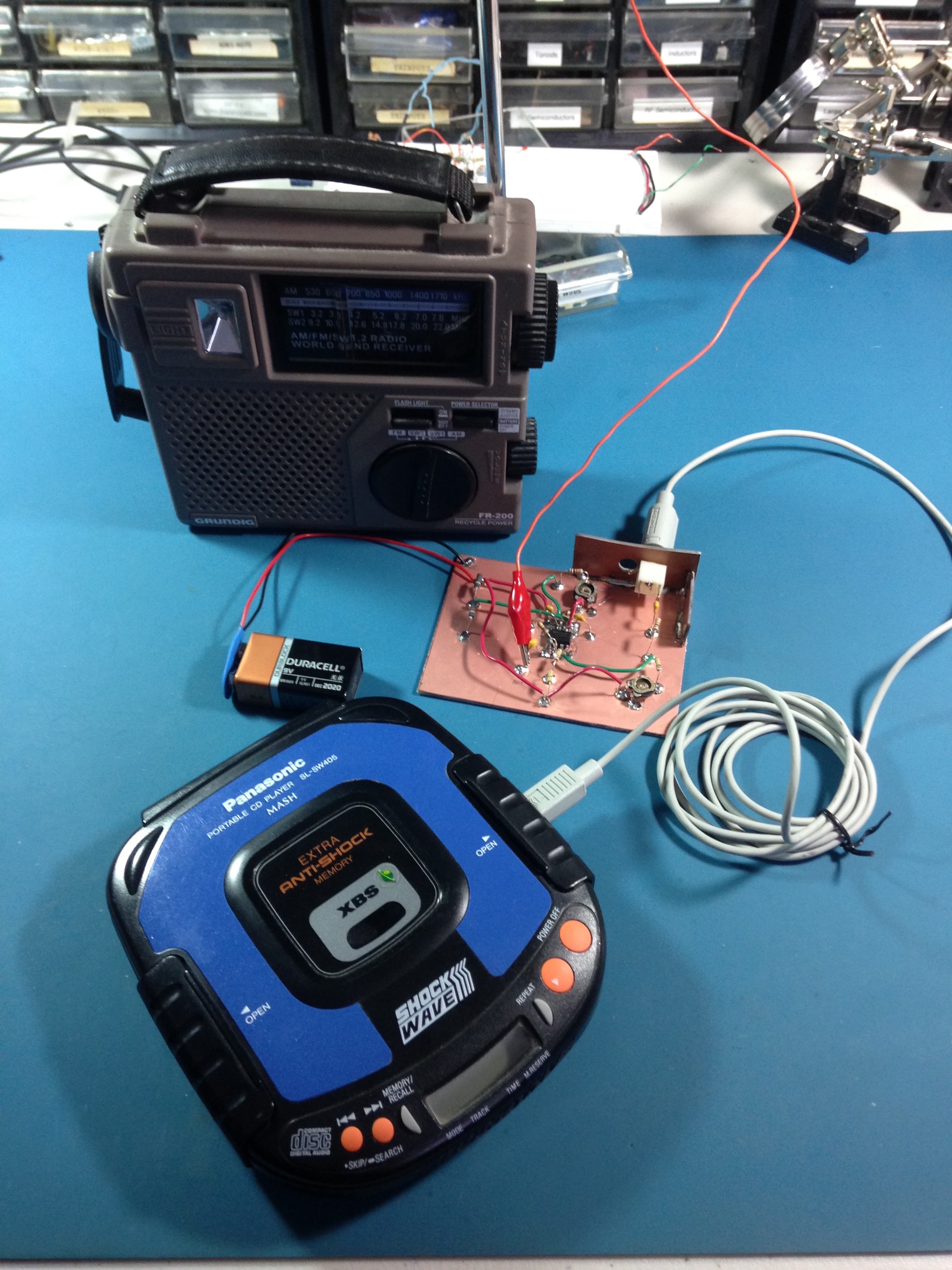
Here’s a practical example from last summer: I wanted to test the performance of a radio that receives signals in the AM broadcast band, between roughly 500-1600 MHz, but in Halifax, Nova Scotia, all of the AM broadcasters have vacated this band in favour of the FM band. So when you turn on an AM radio in Halifax (during the day, at least), you’ll get noise, hiss, static, but nothing intelligible to a human. So I had to build my own little radio station that would modulate an audio signal from a CD player with a carrier wave around 1000 KHz. Tune the radio to around 1000, and you should hear music (but only if the radio is sitting next to the modulator circuit).

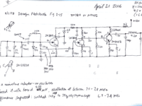
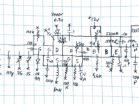
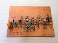
Here’s another example from last Fall: this circuit is from a design by Doug DeMaw W1FB that combines an oscillator with an amplifier. It’s a VFO (variable frequency oscillator) with a buffer amplifier that can be used as a stage in either a transmitter or receiver. The circuit was built on a single-sided PC Board, with islands of copper cut out using a copper engraver’s burin—a tool acquired during my days as a Fine Art Major. The components are soldered onto the islands. The rest of the copper is known as a ‘groundplane’: reserved for connection to zero volts (ground).

Direct conversion receiver

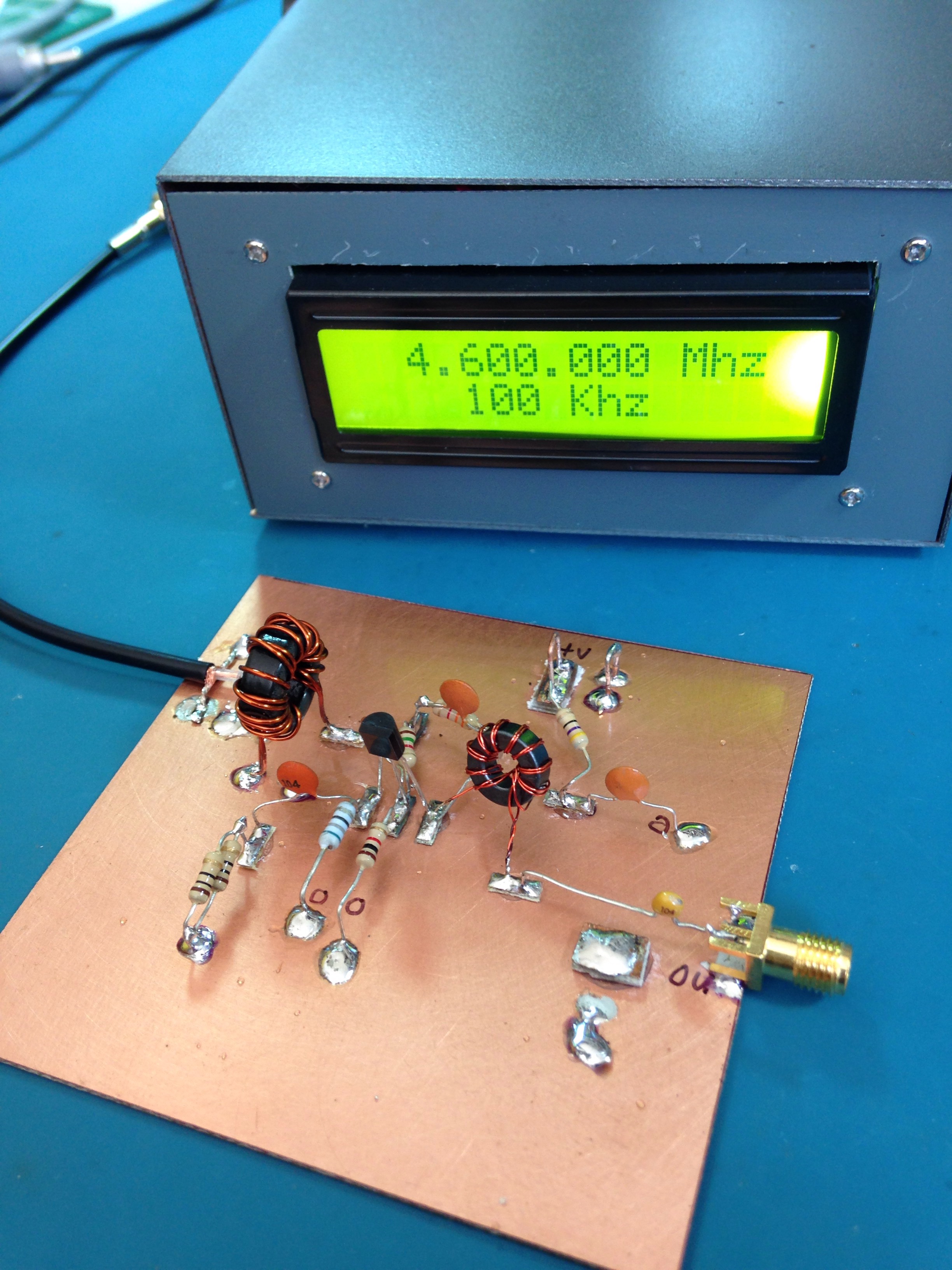
After that, with an increase in confidence, I moved on to building simple radio receivers. The first one used an amplifier design from the book “Crystal Sets to Sideband” by Frank Harris K0IYE. It’s known as a direct conversion receiver, one that’s unusual from most radios we use today because it doesn’t make use of intermediate frequencies to step the signal down from it’s original frequency to audio frequency. The radio is composed of an oscillator an RF board and an AF amplifier.

Direct conversion receiver – close up

The radio signal is brought into the receiver via a coax cable gold connector at the top left. This signal is mixed with a sine wave signal at almost the same frequency as the one we want to tune to. By varying the frequency of the oscillator, we can tune into different frequencies, which will be displayed on the frequency generator unit. When these two signals are combined, the difference frequency is the audio from the radio station. This low-level audio is transferred to the lower board with a short coax cable to the audio amplifier, which drives small earbuds for listening. The battery pack at the top right delivers about 12 volts to the radio.

This report gets me caught up to late October 2016. My next post will introduce “regens“. I realize that I haven’t revealed where all this activity is taking me in my design research. It will come in later posts.

73!

More Experiments in Servo-actuated Frequency Displays

January 23, 2017

Using the circuit from Servo controlling circuit, I breadboarded this:
555 servo control using variable voltage
Results in a clean PWM pulse train, however:
  • with pin 7 on the 555 biased to 1.47v, travel is less than 90 degrees between inputs of .7  and 5 v.

January 26, 2017

Adjusted circuit:
  • the input current determines the rotational range of the servo, so we need to place a trimmer pot there
  • waveform is clean and pulses are spaced at a consistent 22ms apart

January 27, 2017

  • tested circuit on my WBR Regen 31m receiver: results are difficult to repeat with any consistency.
  • circuit loading on radio changes calibration—this would make it difficult to use with different radios
  • loading also affects tuning
  • On the positive side, circuit continues to outperform op-amp and Arduino circuits, with no problems of power supply dropouts

Conclusion

I think that it’s time to go back to the Arduino-controlled circuit to see if I can wrangle the power-dropout-reset issue.


Experiments in Servo-actuated Radio Frequency Displays

Over the past year I’ve been playing with radios. I started by building oscillators, then amplifiers, and then radios.

Regens

WBR

Radios come in all different shapes and sizes, and this also holds true for the circuits inside the radio. One of the earliest radio receiver techniques is called “regeneration”. It was devised by Edwin Armstrong in 1912 when he was still a student at Columbia. This method routes part of the received signal that emerges from an amplifying device back to the input to increase the gain of the circuit. The design was common up to the 1930’s when it was superseded by other more sophisticated methods. However, regen radios have lately had a bit of a comeback with the “internet of things”; your garage door opener receiver is likely a regenerative receiver, for example.

So I’ve been building simple regen radios for various shortwave bands. Some work, some don’t. The latest one is called a “WBR” (Wheatstone Bridge Regen). This one works. I used designs from N1BYT (PDF file) and AA7EE. This particular design is tuned by varying the voltage from a ten-turn potentiometer. My radio tunes from around 9.4 to 10 MHz.

Aliexpress 10-turn potentiometer with a reduction gear

The 10-turn pot results in smooth, very fine tuning, but it’s difficult to know what frequency in this range I’m tuned to. Many older radios have an elaborate system of pulleys and strings that link the rotation of the tuning dial to an indicator. It is possible to buy a 10-turn pot with a reduction gear. They aren’t expensive, but the indicator goes from 0-9 or some arbitrary set of numbers, not the actual tuned frequencies.

Micro-servo

I’ve decided to see if I can use a small servo motor (one that are used in radio controlled helicopters, planes and drones) to turn an indicator dial that accurately reflects the tuned frequency.

Perceived and/or Assumed Drawbacks

I did a cursory search online to see if other experimenters had tried this, and I found nothing. Am I such a divergent thinker that nobody else has thought of doing this? I certainly don’t think so. It’s just that nobody has thought to document their discoveries.

At any rate, I’m assuming that there are several reasons why this technique hasn’t been adopted:

  1. Servo noise may interfere with reception. An increasingly popular method of determining tuned frequency is to add a digital display. Some digital hash may leak into the radio circuits from the display’s digital pulses, but this doesn’t stop experimenters and manufacturers from employing this method in their radios by carefully shielding the digital section from the analog. However servo noise — that is, noise generated by the motor — may be louder than the digital noise that’s produced by the microcontroller and associated digital components, and this may drown out weak radio signals.
  2. The servo motor is power-hungry, making it unsuitable for battery operation.
  3. It may be difficult to consistently align the dial markings to tuning.
  4. Other unknown unknowns.

Follies

My first thought was to control the servo using an Arduino. A quick sketch of the display circuit indicated that I only needed one analog input and one digital PWM output. I was able to breadboard a circuit and loaded in the “Knob” sketch that comes as an example with the Arduino IDE. Everything seemed to work well. But rather than use a larger Atmega328PU chip that has 28 pins—22 of which would be unconnected—I decided to try an ATtiny form factor. I had both an ATtiny45 and an ATtiny85 in the junk box.

ATtiny programmer shield

I built a programming shield for the ATtinys, and managed to successfully flash the Arduino bootloader into them, but the standard Arduino servo library “Knob” sketch would not work on the ATtiny. I spent a day or so trying other libraries but it seems that there’s not been a lot of interest in overcoming this obstacle.

I went back to the junk box and found an Arduino Mini Pro. It’s overkill but it’s at least small enough to install in the radio, and inexpensive compared to an Arduino UNO. So, onto the breadboard it went: the sketch loaded and things were looking up.

The circuit

In this radio, the analog input comes from the wiper arm of the tuning pot, which goes from around 1 volt to 8 volts; the tuning section of the radio uses 8v and the Arduino Mini Pro needs no more than 5v, so I had to build a 5v supply. This signal from the potentiometer goes through a voltage divider to reduce the maximum voltage to 5v to ensure that the analog input pin is not overloaded.

One thing that I found on the breadboarded circuit was that the servo motor would sometimes draw so much current as to reset the microcontroller. This problem was mitigated (somewhat) by adding a low pass filter composed of a small resistance and a large capacitance across the input of the 5v regulator.

Building Notes

Time to build it into the radio and play with it…

LeBlanc’s Law: Wiring errors are proportional to the density of components on the circuit board.

Jan 10
  • attached to receiver: when the motor runs, it draws down the voltage very slightly which causes some receiver noise
  • drawing Arduino current from +12v—does not seem to work if source comes from 8v
  • watch out for LM78L05 pins: pin 1 is output and pin 3 is input!!!
  • watch out for ground loops: be sure to attach Arduino ground close to Arduino +V
  • ISSUE: various noises from servo

Jan 11
  • added a 47Ω resistor in series and 1500µF capacitor in parallel on input to voltage regulator to reduce motor noise

I seem to make one particular recurring mistake when building a final circuit: I don’t use a large enough board. This happens most often when I’ve breadboarded a circuit and I think that the design is done and I can go ahead and solder everything together. But what ends up happening is that I find problems or improvements to the “final” design that then becomes quite difficult to achieve in the close quarters of a crowded circuit. That, plus the fact that wiring errors are more likely as density of components increases, caused a relatively simple task that should have taken less than an hour to take days (well, not literally) of troubleshooting.

Initial calibration was performed by feeding in signals between 9.4 and 10MHz using a DDS sine wave generator through a -30db attenuator, and locating them on the tuning dial. I’ve not done any subsequent calibrations to see if the tuning indications vary over time.

Experiment Notes

Jan 13 & 14:

Hiccupping

As I moved the components from the breadboard to the perfboard, the device became unreliable. This may have been because I connected the servo improperly. When tuning quickly, it seemed like the controller would reset, causing hiccupping. I replaced the Arduino Mini Pro with a new one and it worked fairly well for a few minutes but it later exhibited the same issues. Could it be starved of current when the servo motor is actuated?

The device no longer delivers PWM to the servo. Could this one be broken too? If so, what would cause this?

Jan 15:
16:45 – Found the problem: power not getting to the regulator.
17:15 – Only problem now is “surging” when the tuning knob is turned quickly, especially at the higher end of the voltage scale.
17:45 – Now it doesn’t work. No PWM from pin 9.
18:10 – It’s working now: Connected RST to VCC. Apparently RST pin was floating, causing the device to go into permanent reset. Keeping it at VCC prevents that. The reset button on the unit still works.

Conclusions

  1. Input voltages between 4 and 5 volts seem to make the servo hesitate and surge. This could be attributed to the 78L05–replacing it with a (higher current) 7805 regulator might fix this.
  2. Sometimes the servo hunts. It should be possible to turn off the servo once it has moved to the correct location.
  3. It’s difficult to calibrate the display. It may be possible to add trimmer resistors to the voltage divider that would permit better calibration.
  4. The servo isn’t completely silent and may become annoying, especially when the listener is trying to copy weak signals out of the noise floor.
  5. Why use a microcontroller? Is there a more “analog” circuit component that could be used instead?
  6. More experimentation is warranted…