Over the past year I’ve been playing with radios. I started by building oscillators, then amplifiers, and then radios.
Regens
WBR
Radios come in all different shapes and sizes, and this also holds true for the circuits inside the radio. One of the earliest radio receiver techniques is called “regeneration”. It was devised by Edwin Armstrong in 1912 when he was still a student at Columbia. This method routes part of the received signal that emerges from an amplifying device back to the input to increase the gain of the circuit. The design was common up to the 1930’s when it was superseded by other more sophisticated methods. However, regen radios have lately had a bit of a comeback with the “internet of things”; your garage door opener receiver is likely a regenerative receiver, for example.
So I’ve been building simple regen radios for various shortwave bands. Some work, some don’t. The latest one is called a “WBR” (Wheatstone Bridge Regen). This one works. I used designs from N1BYT (PDF file) and AA7EE. This particular design is tuned by varying the voltage from a ten-turn potentiometer. My radio tunes from around 9.4 to 10 MHz.
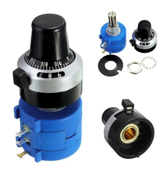
Aliexpress 10-turn potentiometer with a reduction gear
The 10-turn pot results in smooth, very fine tuning, but it’s difficult to know what frequency in this range I’m tuned to. Many older radios have an elaborate system of pulleys and strings that link the rotation of the tuning dial to an indicator. It is possible to buy a 10-turn pot with a reduction gear. They aren’t expensive, but the indicator goes from 0-9 or some arbitrary set of numbers, not the actual tuned frequencies.
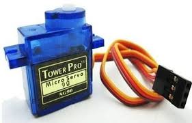
Micro-servo
I’ve decided to see if I can use a small servo motor (one that are used in radio controlled helicopters, planes and drones) to turn an indicator dial that accurately reflects the tuned frequency.
Perceived and/or Assumed Drawbacks
I did a cursory search online to see if other experimenters had tried this, and I found nothing. Am I such a divergent thinker that nobody else has thought of doing this? I certainly don’t think so. It’s just that nobody has thought to document their discoveries.
At any rate, I’m assuming that there are several reasons why this technique hasn’t been adopted:
Servo noise may interfere with reception. An increasingly popular method of determining tuned frequency is to add a digital display. Some digital hash may leak into the radio circuits from the display’s digital pulses, but this doesn’t stop experimenters and manufacturers from employing this method in their radios by carefully shielding the digital section from the analog. However servo noise — that is, noise generated by the motor — may be louder than the digital noise that’s produced by the microcontroller and associated digital components, and this may drown out weak radio signals.
The servo motor is power-hungry, making it unsuitable for battery operation.
It may be difficult to consistently align the dial markings to tuning.
Other unknown unknowns.
Follies
My first thought was to control the servo using an Arduino. A quick sketch of the display circuit indicated that I only needed one analog input and one digital PWM output. I was able to breadboard a circuit and loaded in the “Knob” sketch that comes as an example with the Arduino IDE. Everything seemed to work well. But rather than use a larger Atmega328PU chip that has 28 pins—22 of which would be unconnected—I decided to try an ATtiny form factor. I had both an ATtiny45 and an ATtiny85 in the junk box.
ATtiny programmer shield
I built a programming shield for the ATtinys, and managed to successfully flash the Arduino bootloader into them, but the standard Arduino servo library “Knob” sketch would not work on the ATtiny. I spent a day or so trying other libraries but it seems that there’s not been a lot of interest in overcoming this obstacle.
I went back to the junk box and found an Arduino Mini Pro. It’s overkill but it’s at least small enough to install in the radio, and inexpensive compared to an Arduino UNO. So, onto the breadboard it went: the sketch loaded and things were looking up.
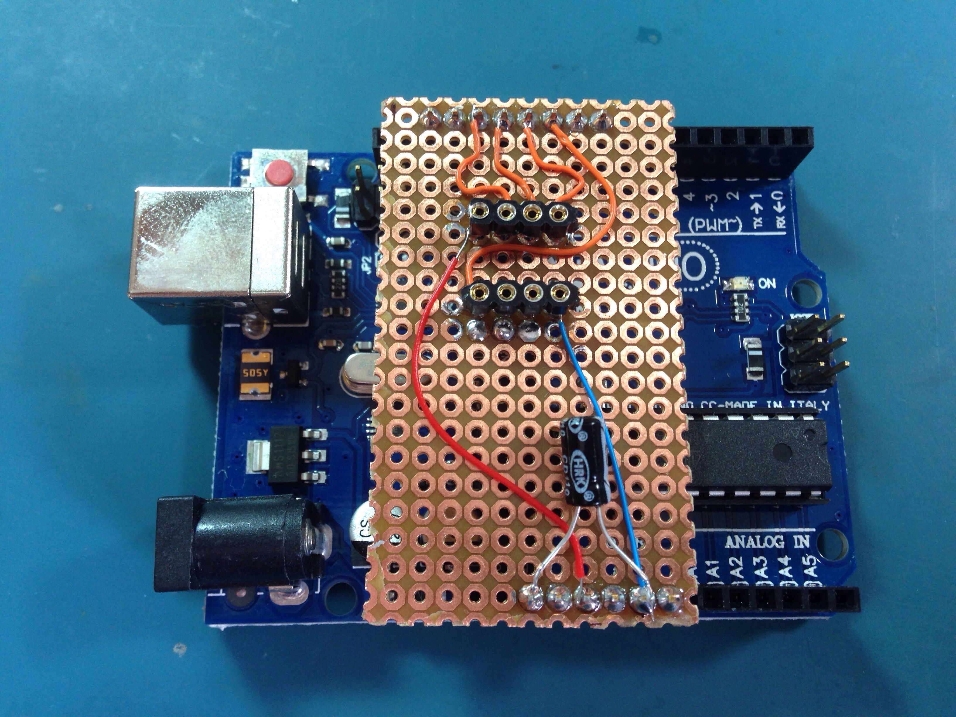
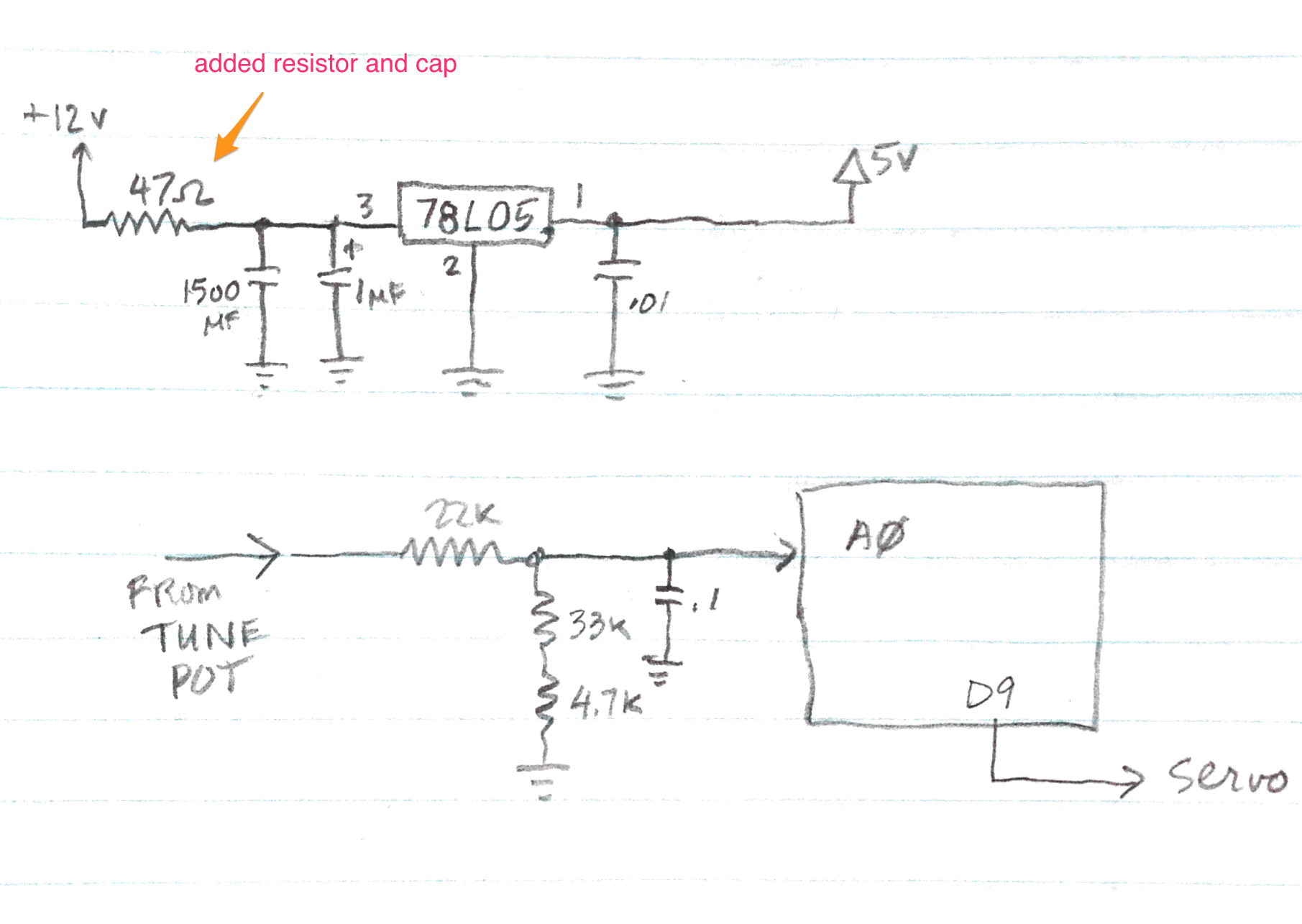
The circuit
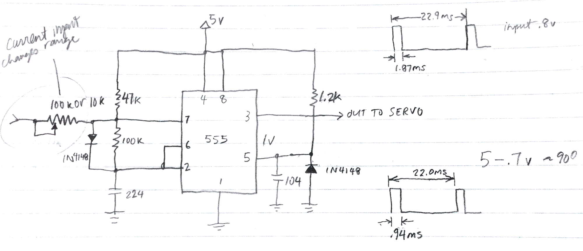
In this radio, the analog input comes from the wiper arm of the tuning pot, which goes from around 1 volt to 8 volts; the tuning section of the radio uses 8v and the Arduino Mini Pro needs no more than 5v, so I had to build a 5v supply. This signal from the potentiometer goes through a voltage divider to reduce the maximum voltage to 5v to ensure that the analog input pin is not overloaded.
One thing that I found on the breadboarded circuit was that the servo motor would sometimes draw so much current as to reset the microcontroller. This problem was mitigated (somewhat) by adding a low pass filter composed of a small resistance and a large capacitance across the input of the 5v regulator.
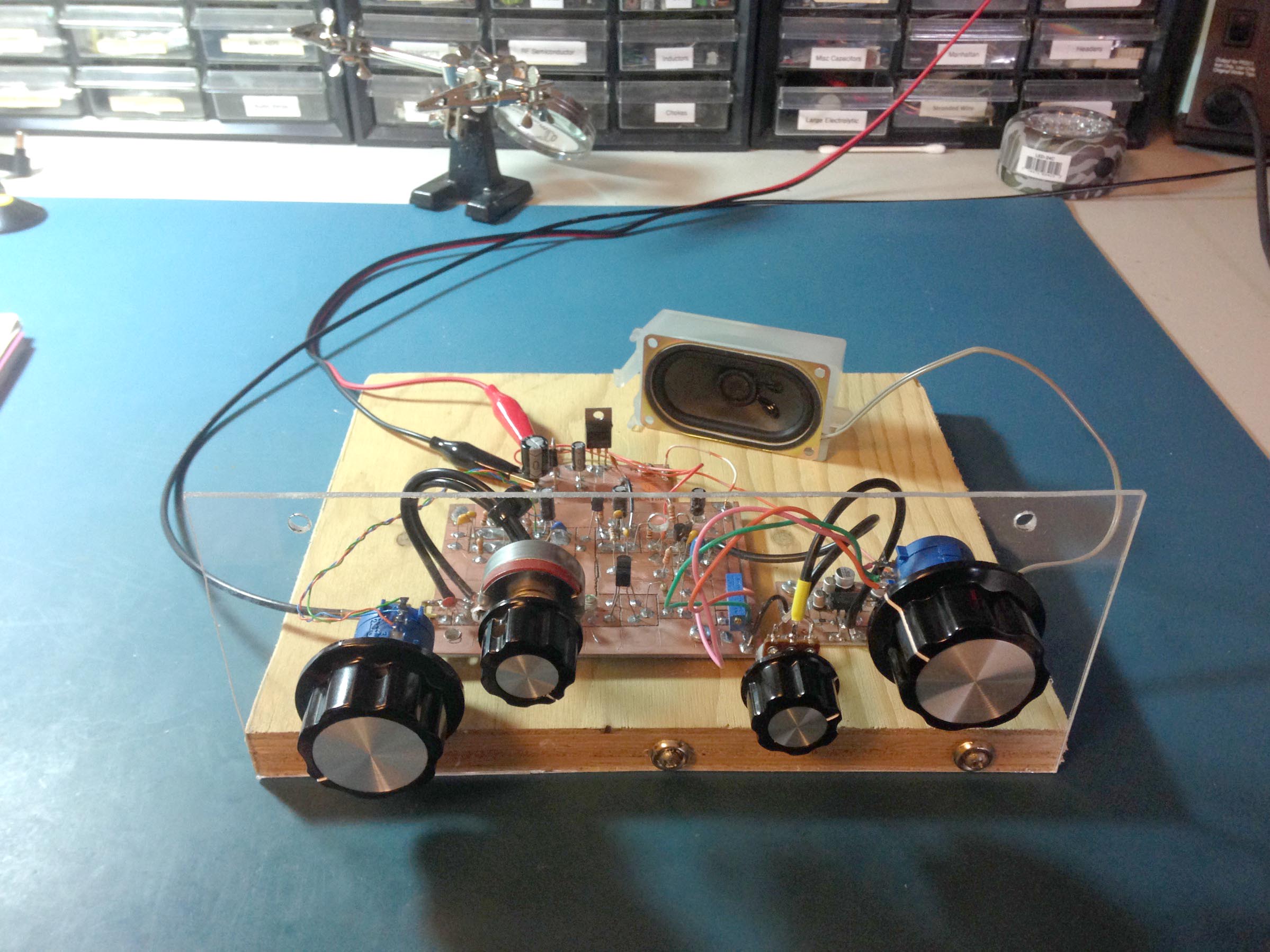
Building Notes
Time to build it into the radio and play with it…
LeBlanc’s Law: Wiring errors are proportional to the density of components on the circuit board.
Jan 10
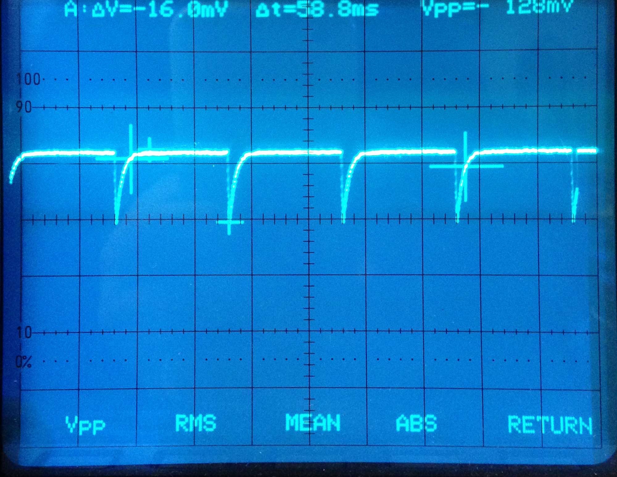
attached to receiver: when the motor runs, it draws down the voltage very slightly which causes some receiver noise
drawing Arduino current from +12v—does not seem to work if source comes from 8v
watch out for LM78L05 pins: pin 1 is output and pin 3 is input!!!
watch out for ground loops: be sure to attach Arduino ground close to Arduino +V
ISSUE: various noises from servo
Jan 11
added a 47Ω resistor in series and 1500µF capacitor in parallel on input to voltage regulator to reduce motor noise
I seem to make one particular recurring mistake when building a final circuit: I don’t use a large enough board. This happens most often when I’ve breadboarded a circuit and I think that the design is done and I can go ahead and solder everything together. But what ends up happening is that I find problems or improvements to the “final” design that then becomes quite difficult to achieve in the close quarters of a crowded circuit. That, plus the fact that wiring errors are more likely as density of components increases, caused a relatively simple task that should have taken less than an hour to take days (well, not literally) of troubleshooting.
Initial calibration was performed by feeding in signals between 9.4 and 10MHz using a DDS sine wave generator through a -30db attenuator, and locating them on the tuning dial. I’ve not done any subsequent calibrations to see if the tuning indications vary over time.
Experiment Notes
Jan 13 & 14:
Hiccupping
As I moved the components from the breadboard to the perfboard, the device became unreliable. This may have been because I connected the servo improperly. When tuning quickly, it seemed like the controller would reset, causing hiccupping. I replaced the Arduino Mini Pro with a new one and it worked fairly well for a few minutes but it later exhibited the same issues. Could it be starved of current when the servo motor is actuated?
The device no longer delivers PWM to the servo. Could this one be broken too? If so, what would cause this?
Jan 15:
16:45 – Found the problem: power not getting to the regulator.
17:15 – Only problem now is “surging” when the tuning knob is turned quickly, especially at the higher end of the voltage scale.
17:45 – Now it doesn’t work. No PWM from pin 9.
18:10 – It’s working now: Connected RST to VCC. Apparently RST pin was floating, causing the device to go into permanent reset. Keeping it at VCC prevents that. The reset button on the unit still works.
Conclusions
Input voltages between 4 and 5 volts seem to make the servo hesitate and surge. This could be attributed to the 78L05–replacing it with a (higher current) 7805 regulator might fix this.
Sometimes the servo hunts. It should be possible to turn off the servo once it has moved to the correct location.
It’s difficult to calibrate the display. It may be possible to add trimmer resistors to the voltage divider that would permit better calibration.
The servo isn’t completely silent and may become annoying, especially when the listener is trying to copy weak signals out of the noise floor.
Why use a microcontroller? Is there a more “analog” circuit component that could be used instead?
Well, hello there. It was a long, dreadful, record-breaking winter here in Nova Scotia. Although most of the snow has melted, it’s still unseasonably cold. I heard on local radio today that people are calling it “springter”. My last post was in October, and since then I’ve been occupied with teaching, promoting NSCAD programs in China and chairing an academic department; things that are either not blog-worthy or worth repeating publicly.
Weather Sensing Invention
Around the time of my last post, I had stumbled upon what I think might be a new invention relating to weather sensing. With the help of Kevin Buchan, NSCAD’s research consultant, I issued a proposal to Innovacorp for an Early Stage Commercialization Fund grant to help develop a working prototype. I heard at the end of February that I didn’t get the grant, so that’s off the table for the moment. By the way, my friend and colleague Sol Nagler received funding for his “Narratives – A Geolocative Interactive Storytelling Mobile Application” project. At least, I thought he was my friend. 😉
Radio
Over the past number of years, I’ve been utilizing tiny RFM12 and RFM12B 434 MHz radio units to send and receive sensor data around the house. These units use Arduino ATMEGA 328 microcontrollers and the Jeenode Library. I hope to talk more about this long-term project in future posts.
The more I worked with these magical devices, the more interested I became in their inner workings. Specifically, I wanted to know:
how to get the RF energy from the little circuit out to the world
what kinds of environmental factors affect the propagation of the RF energy
how to maximize and direct the RF energy from the sensor to a base receiver
However, in my research I was confronted with a wall of my own ignorance; as I searched for answers, more questions kept popping up. So I decided to undertake a long-term study, and as part of that plan I applied for my amateur radio license. I took the test on March 31 and received my Basic with Honours license, which allows me to use all of the HF, VHF and above amateur radio bands using standard commercially-designed and built radios. I want to be able to design and build my own transmitters, but that will have to wait until I can pass the Advanced license test. My callsign is VE1LEB. The VE1 prefix indicates my location as Nova Scotia, Canada.
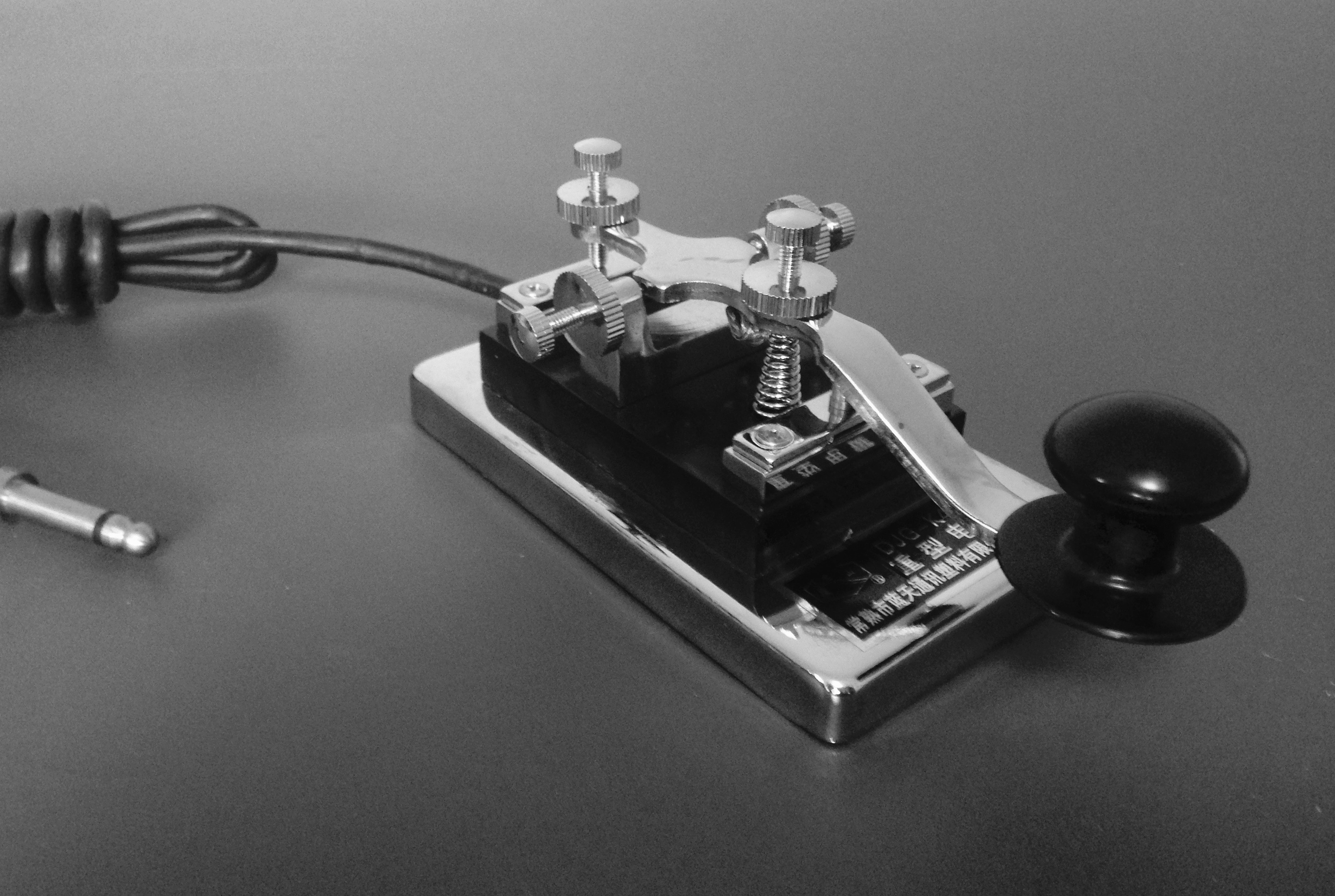
Changshu K-4 Heavy Key
So what’s the “Military Room Escape Movie Prop”? It comes from the AliExpress listing for a Chinese Army Changshu K-4 morse code key that I received in the mail yesterday. These keys have been in service in the Chinese military from the early 1960’s. It weighs one kilogram and it’s a thing of beauty! Morse code hasn’t been a requirement for amateur radio licensing in Canada for ten years, but I’m learning to send and receive anyway and hope to take the 5 wpm test in the Fall to get this function added to my certification.