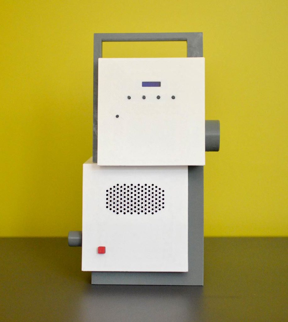
In the late winter of 2018-19, I decided to build a receiver that would provide a performance improvement to the regen I built a couple of years ago. I wanted the radio to receive AM and SSB signals between 160m and 20m (1.8-14.5 MHz).
Another regen seemed to be out of the question; although regens are very sensitive, they have other drawbacks: they’re difficult to tune, and once tuned, the configuration needs to be changed often to prevent howls of oscillation and other audio problems.
It made sense to me that the next step in my radio-building self-instruction should be a ‘direct conversion’ receiver. DC radios have an oscillator running at the same frequency as the signal you’re trying to receive. This oscillating wave gets combined with the signal in a double-balanced mixer. The mixer converts the high-frequency signal down to audio frequency, where it can be amplified using several audio amp stages. It’s a very simple configuration, and the result is a very clean sound.
The DC radio can also be fitted with a frequency display, which is in this case is an Arduino that controls an SI5351 oscillator at the frequency I want to listen to, and a digital display that shows the frequency I’m tuned to.
Design
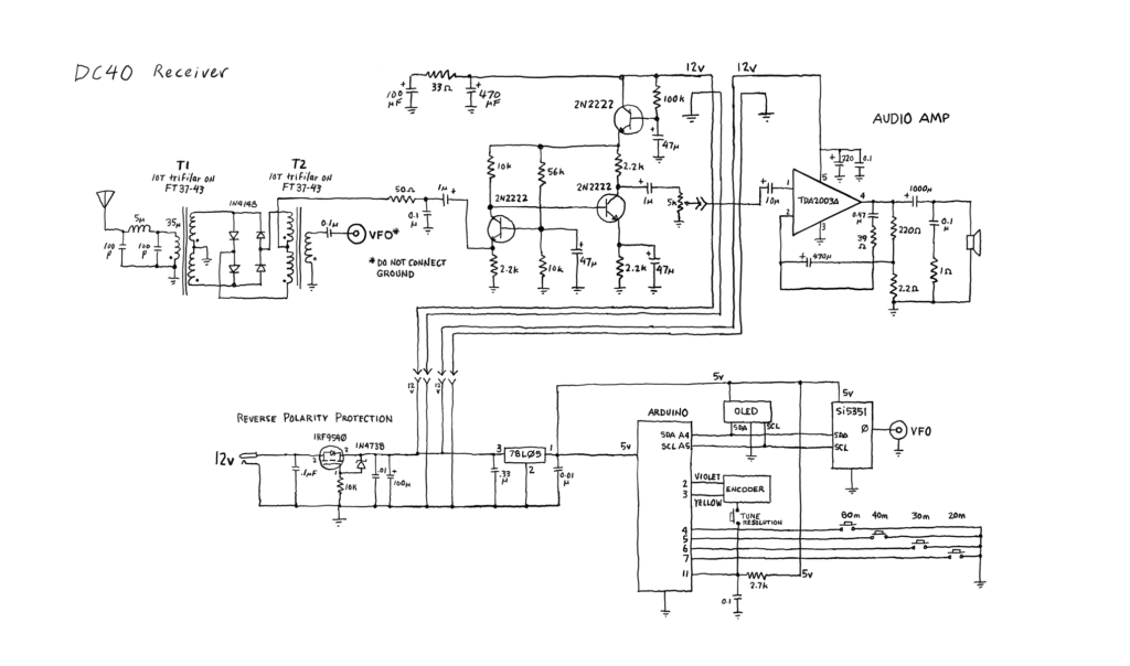
The basic design comes from Farhan VU2ESE, with modifications by Ryan Flowers. I used a different audio amplifier than the ones specified in the original plans. I tried an LM381 preamp and an LM386 but was unhappy with the results. The amplified audio coming out of the LM386 was barely enough to power a speaker and could only be used with headphones. I tried several different audio amplifiers and finally settled on the TDA2003A.
I faced difficulty with hum and there was a tendency for the audio amp to self-oscillate. I added a power line filter, which helped a little, but the best results seem to be to use battery power. Self-oscillation is still somewhat of an issue with the TDA2003 at max volume. You can see from the schematic that I tried to gather 0v (ground) for both the digital and audio sections to a common point, which should help in reducing hum and other problems.
This was the first opportunity I had to experiment with homebrewed double-balanced mixers. I used four closely-matched germanium diodes for the diode ring.
Another first for me: a reverse polarity protection circuit—using an IRF9540 P-channel MOSFET—is placed between the +13v power socket and the rest of the radio. It delivers full power with no voltage drop.
The DC40 is tuned using a digital encoder. I initially tried a cheap $3.00 encoder but wasn’t at all happy with the feel. Instead I ordered a Bourns EM14 optical encoder from Arrow that provides 64 pulses per revolution. By the way, my experience with Arrow has been very positive, despite the fact that the order wasn’t shipped until I contacted them two weeks after placing it, and then the shipping container for the encoder arrived slightly opened and empty. Support was excellent however and a replacement arrived two days later. Other stuff ordered from Arrow has been on time and in perfect shape.
Construction
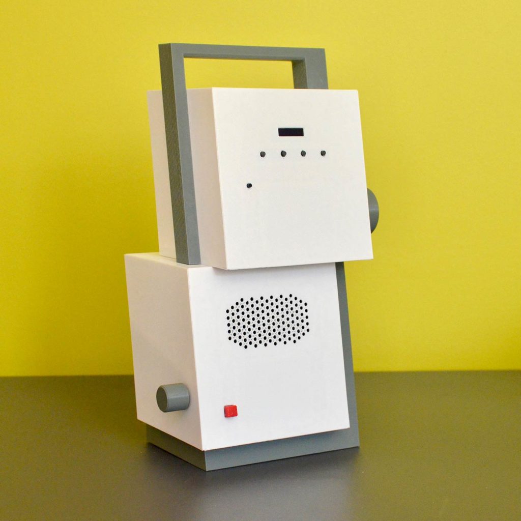
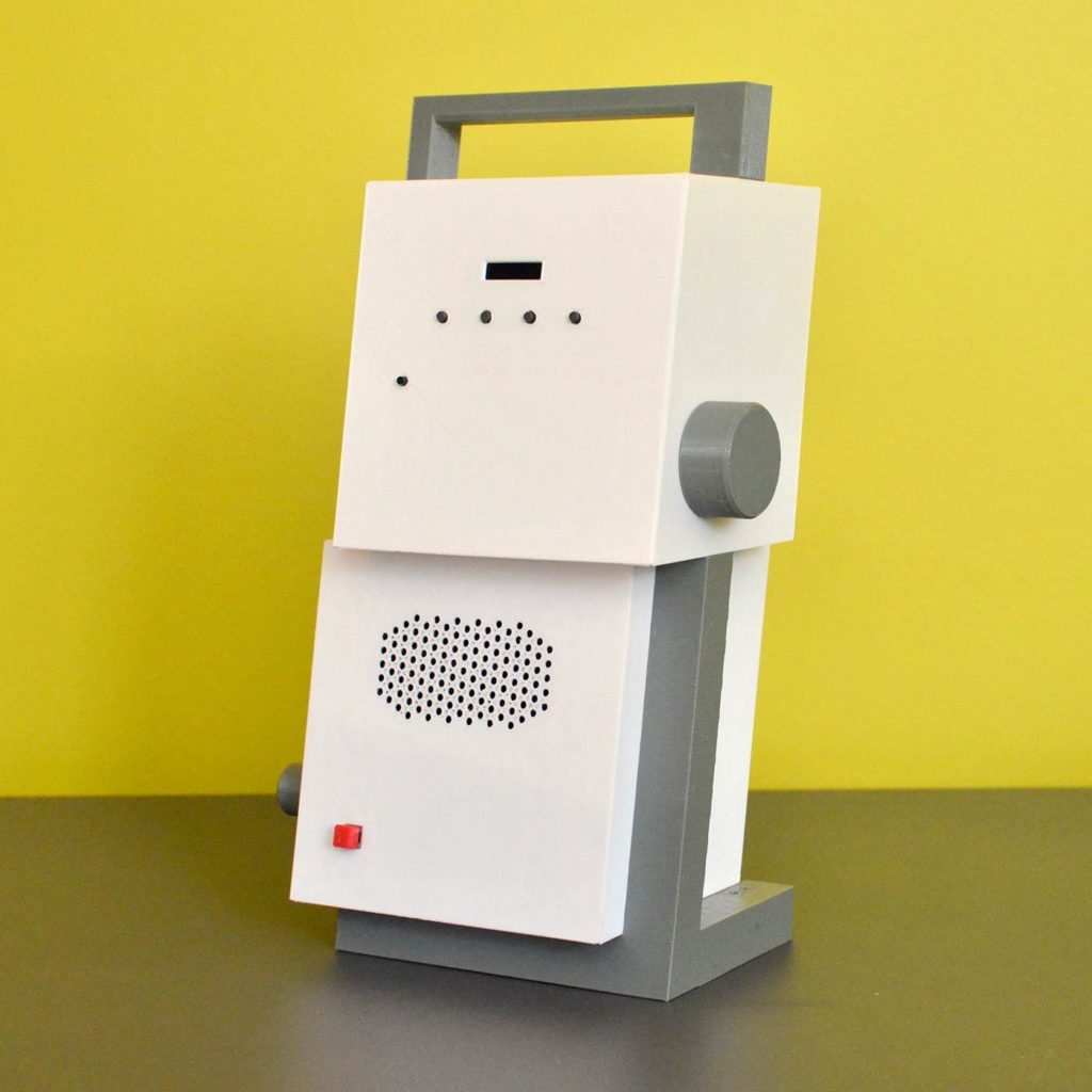
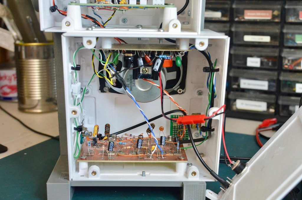
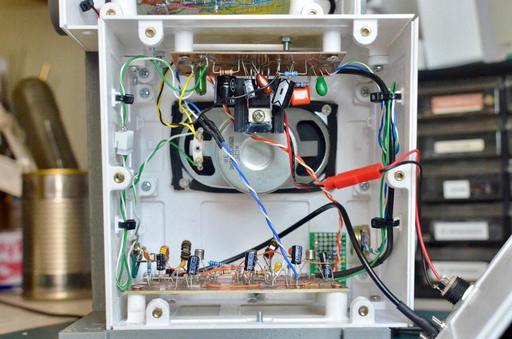
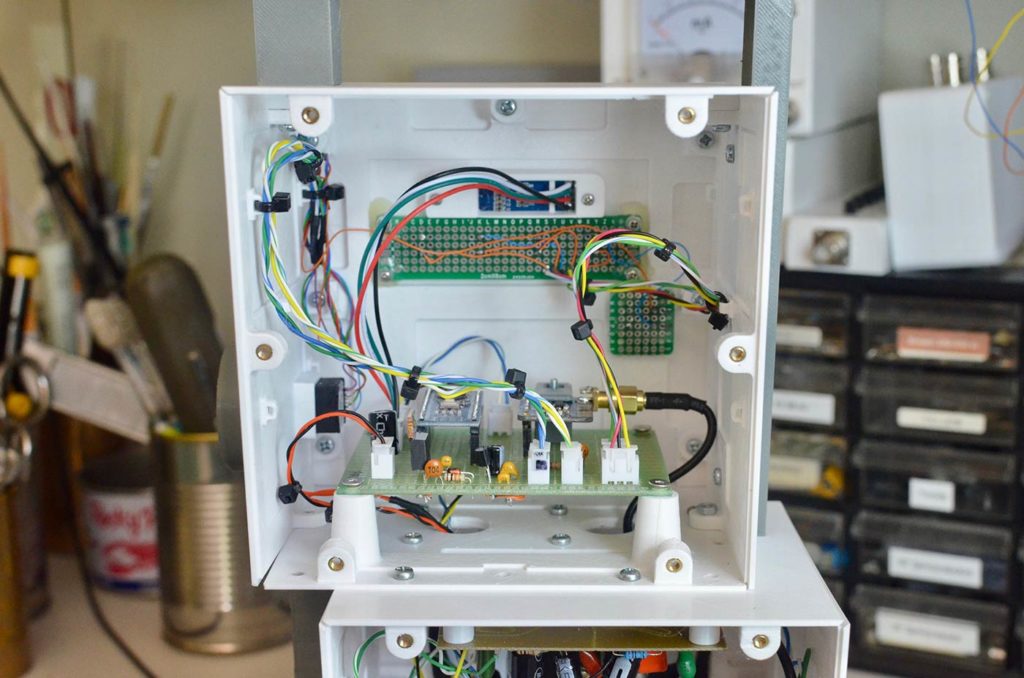
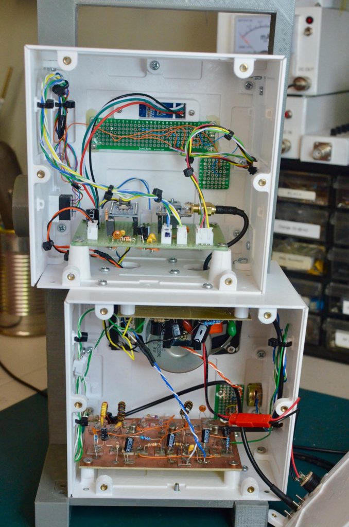
The radio is enclosed in two boxes, one for analog and the other for digital circuits; to avoid interference between the digital signals and the analog radio signals, the components are placed on separate boards. Digital circuits are on the top box and the radio/audio circuits are in the lower box.
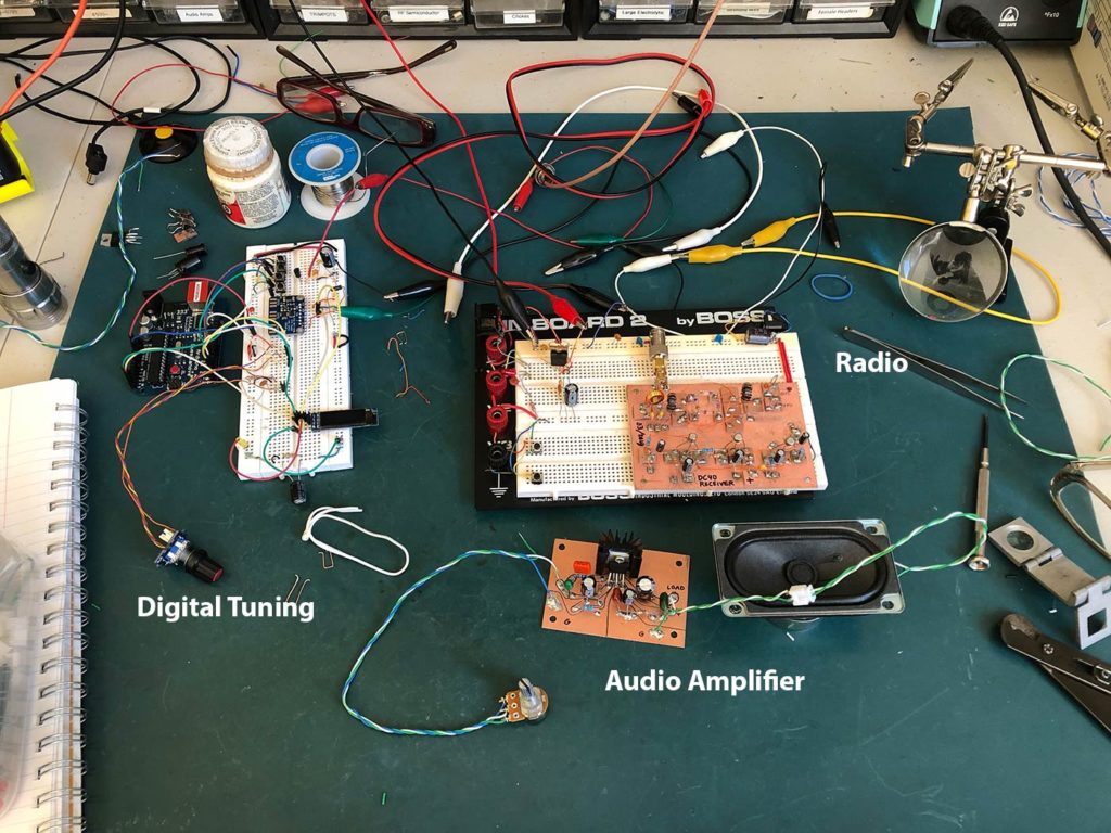
Enclosure
The enclosure was designed using Autodesk Fusion360 and 3D printed using PETG filament on my Prusa i3 Mk2.
In contrast to my previous and previous 3D modeled enclosures, this one is designed so that each facet of each box is printed separately and later bolted together. Because each facet is printed face-down, the surface is very smooth and flat. The disadvantage to this approach is the “bolting-together” bit.
One might use the term ‘nightmare’ to describe it. Although Fusion360 makes it easy to ensure that parts mate well, it was up to me and my tiny brain to try to visualize how I would be able to bolt the pieces together. To my credit, for the most part my design ensures that I could torque each screw without other parts of the enclosure interfering—if I assembled things in the correct order. However, multiple times during assembly I had to disassemble parts because the arrangement obscured or interfered with other connections that had to be made.
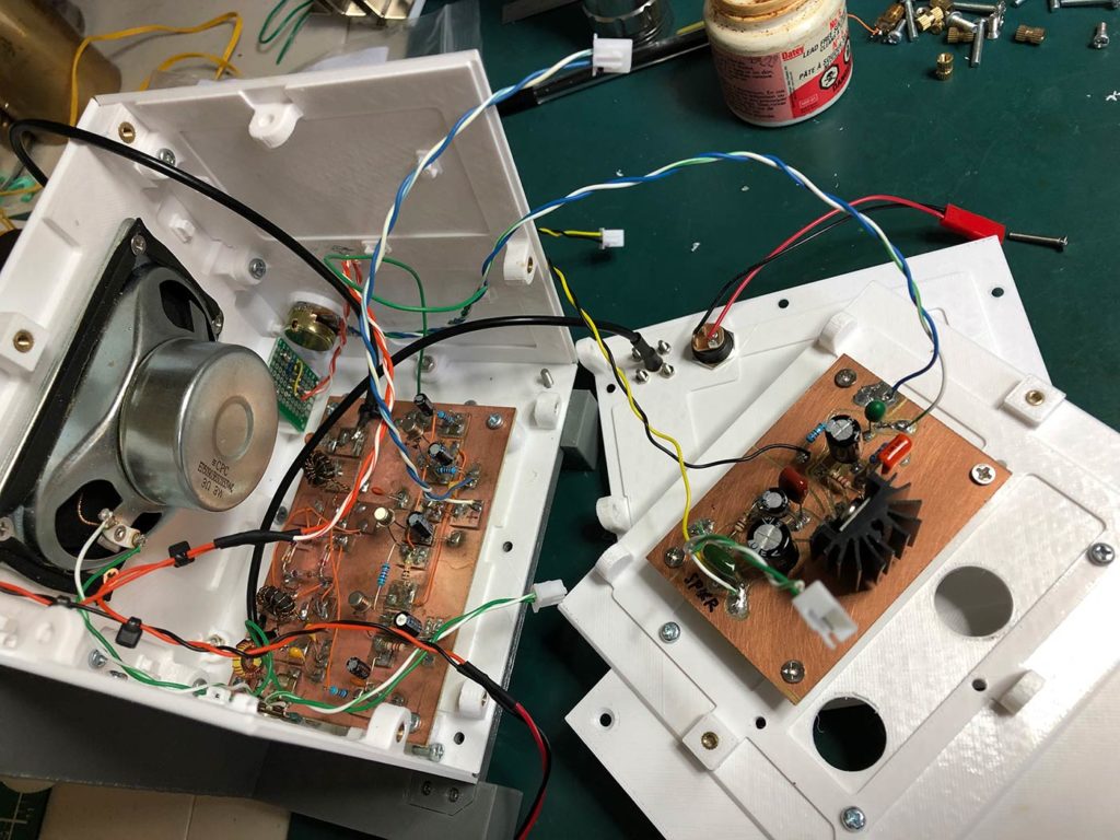
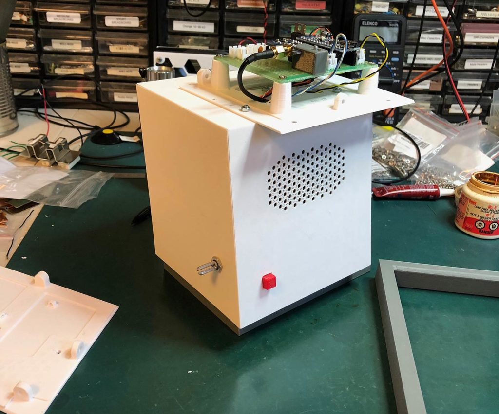
However, over the course of a few days, I was able to fitfully achieve complete assembly. I incorporated holds on the insides of some of the facets to facilitate using nylon ties to organize the inter-board wiring.
Here’s video of the radio in operation:
Michel,
mHz => miliHertz,
MHz => MegaHertz
😉