Tag Archives: electronics

DC40 Receiver

In the late winter of 2018-19, I decided to build a receiver that would provide a performance improvement to the regen I built a couple of years ago. I wanted the radio to receive AM and SSB signals between 160m and 20m (1.8-14.5 MHz).

Another regen seemed to be out of the question; although regens are very sensitive, they have other drawbacks: they’re difficult to tune, and once tuned, the configuration needs to be changed often to prevent howls of oscillation and other audio problems.

It made sense to me that the next step in my radio-building self-instruction should be a ‘direct conversion’ receiver. DC radios have an oscillator running at the same frequency as the signal you’re trying to receive. This oscillating wave gets combined with the signal in a double-balanced mixer. The mixer converts the high-frequency signal down to audio frequency, where it can be amplified using several audio amp stages. It’s a very simple configuration, and the result is a very clean sound.

The DC radio can also be fitted with a frequency display, which is in this case is an Arduino that controls an SI5351 oscillator at the frequency I want to listen to, and a digital display that shows the frequency I’m tuned to.

Design

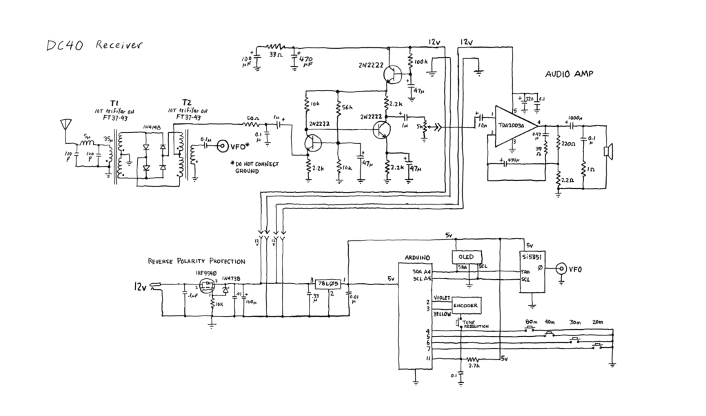
The basic design comes from Farhan VU2ESE, with modifications by Ryan Flowers. I used a different audio amplifier than the ones specified in the original plans. I tried an LM381 preamp and an LM386 but was unhappy with the results. The amplified audio coming out of the LM386 was barely enough to power a speaker and could only be used with headphones. I tried several different audio amplifiers and finally settled on the TDA2003A.

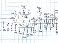
I faced difficulty with hum and there was a tendency for the audio amp to self-oscillate. I added a power line filter, which helped a little, but the best results seem to be to use battery power. Self-oscillation is still somewhat of an issue with the TDA2003 at max volume. You can see from the schematic that I tried to gather 0v (ground) for both the digital and audio sections to a common point, which should help in reducing hum and other problems.

This was the first opportunity I had to experiment with homebrewed double-balanced mixers. I used four closely-matched germanium diodes for the diode ring.

Another first for me: a reverse polarity protection circuit—using an IRF9540 P-channel MOSFET—is placed between the +13v power socket and the rest of the radio. It delivers full power with no voltage drop.

The DC40 is tuned using a digital encoder. I initially tried a cheap $3.00 encoder but wasn’t at all happy with the feel. Instead I ordered a Bourns EM14 optical encoder from Arrow that provides 64 pulses per revolution. By the way, my experience with Arrow has been very positive, despite the fact that the order wasn’t shipped until I contacted them two weeks after placing it, and then the shipping container for the encoder arrived slightly opened and empty. Support was excellent however and a replacement arrived two days later. Other stuff ordered from Arrow has been on time and in perfect shape.

Construction

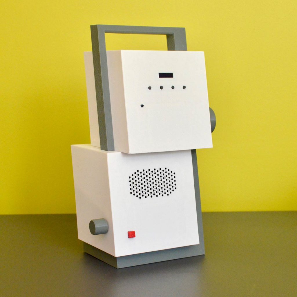
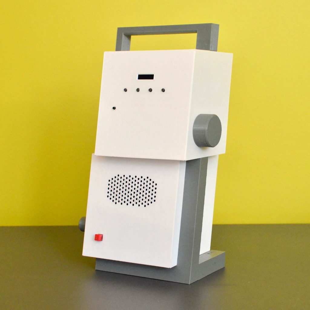
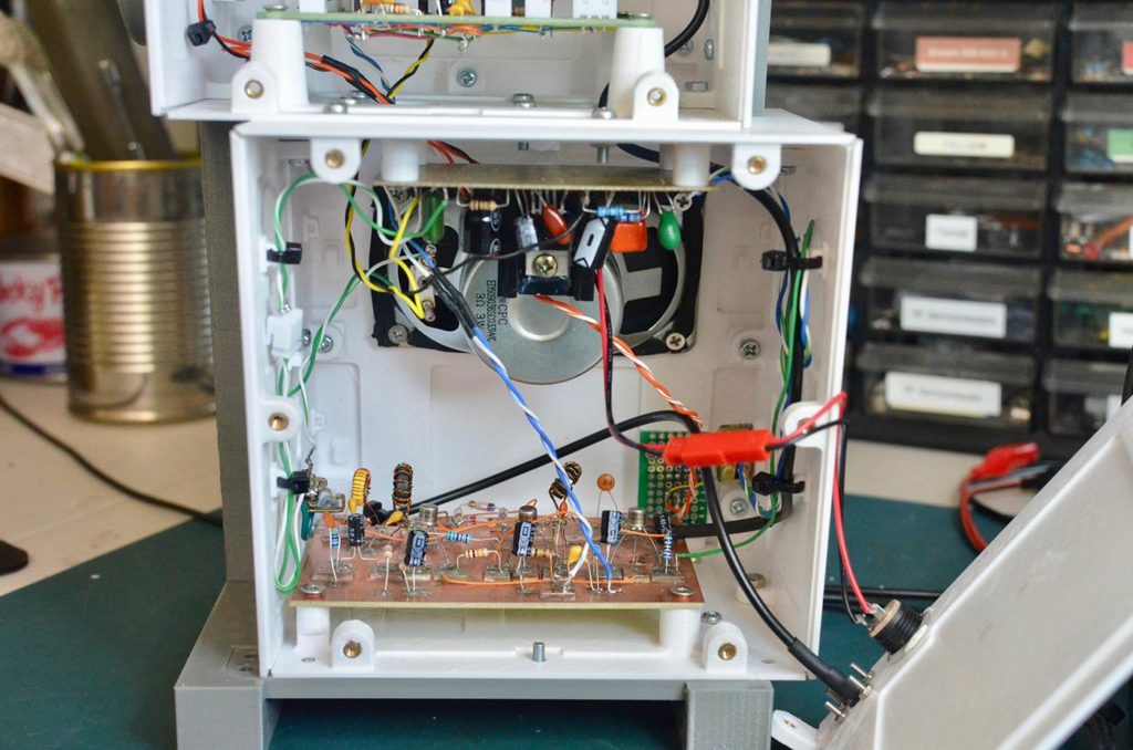
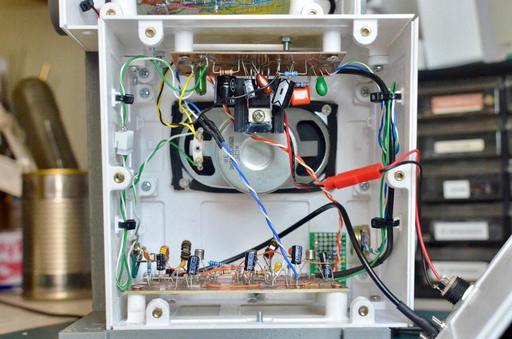
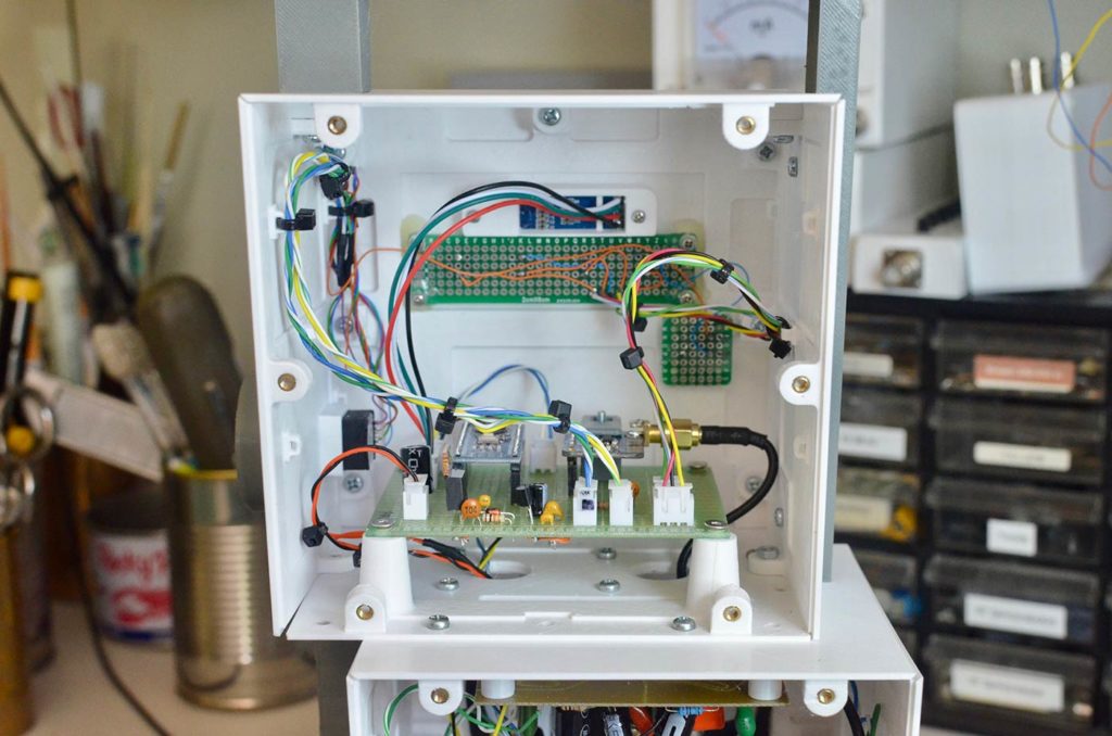
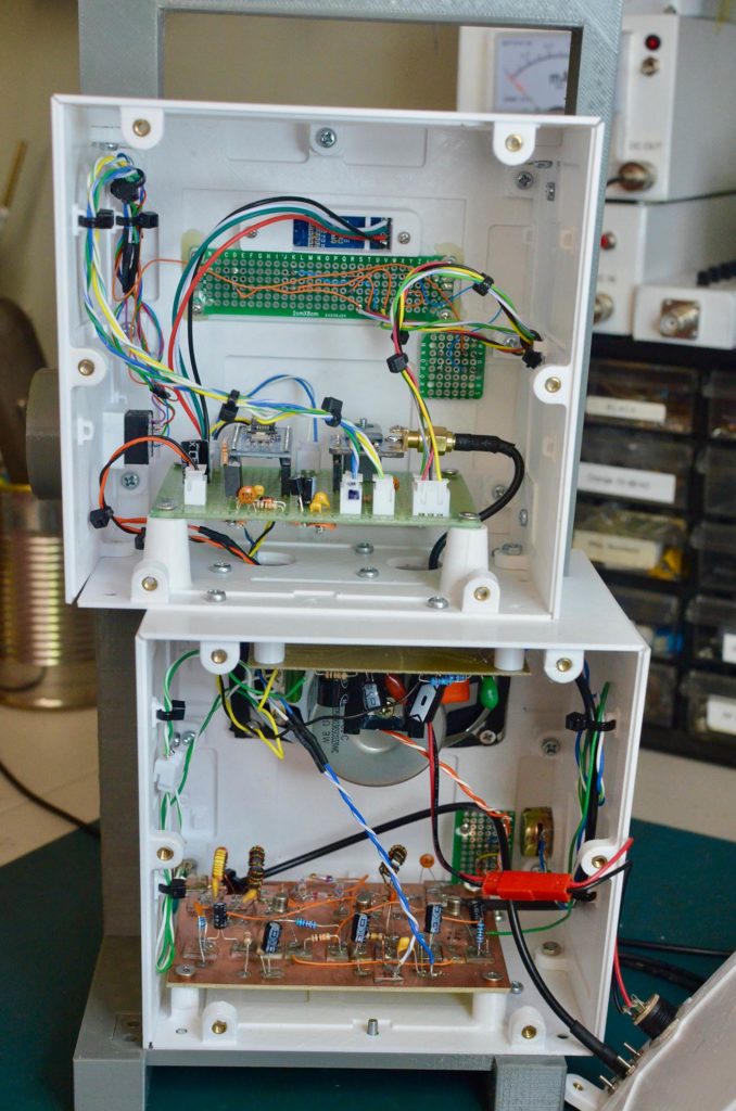
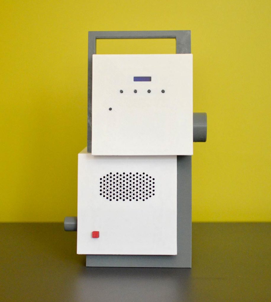
The radio is enclosed in two boxes, one for analog and the other for digital circuits; to avoid interference between the digital signals and the analog radio signals, the components are placed on separate boards. Digital circuits are on the top box and the radio/audio circuits are in the lower box.
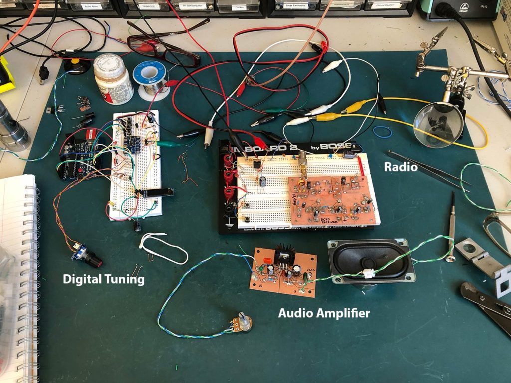
DC40 under construction
The radio ‘al fresco’, with the tuning section on the breadboard at the left, and the completed radio- and audio-frequency boards on the right.

Enclosure

The enclosure was designed using Autodesk Fusion360 and 3D printed using PETG filament on my Prusa i3 Mk2.

In contrast to my previous and previous 3D modeled enclosures, this one is designed so that each facet of each box is printed separately and later bolted together. Because each facet is printed face-down, the surface is very smooth and flat. The disadvantage to this approach is the “bolting-together” bit.

One might use the term ‘nightmare’ to describe it. Although Fusion360 makes it easy to ensure that parts mate well, it was up to me and my tiny brain to try to visualize how I would be able to bolt the pieces together. To my credit, for the most part my design ensures that I could torque each screw without other parts of the enclosure interfering—if I assembled things in the correct order. However, multiple times during assembly I had to disassemble parts because the arrangement obscured or interfered with other connections that had to be made.
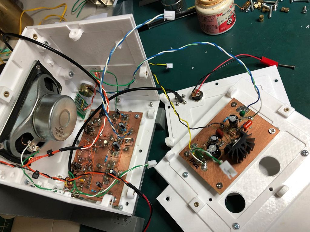
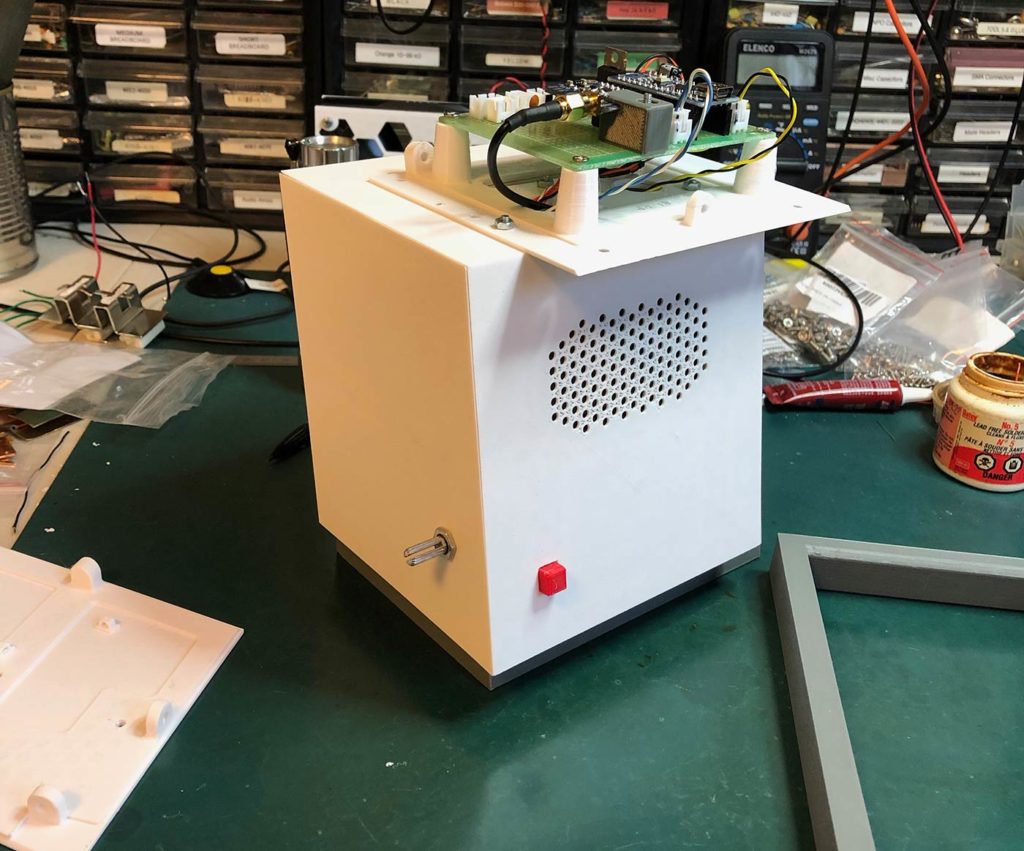
DC40 under construction
Assembling the lower box.
DC40 under construction
The lower box assembled, with the digital board.

However, over the course of a few days, I was able to fitfully achieve complete assembly. I incorporated holds on the insides of some of the facets to facilitate using nylon ties to organize the inter-board wiring.

Here’s video of the radio in operation:
Desert Ratt 2 (First Build)

Paul Harden NA5N designed the Desert Ratt shortwave regen receiver in the mid-1990’s. It’s a popular radio for builders, and my choice was due to the excellent documentation and the fact that it was designed to tune using varactor diodes, rather than metal fin variable capacitors (that were used in the original Desert Ratt).

Here’s my construction journal:

March 4: Started with the LM386 and the transistor preamp, could not get it to chooch. Reverted to the breadboard. AA7EE has pin 7 unconnected. There’s a principle that you should start with the audio amp and work backwards; this doesn’t work as expected because (as I found out), I needed to bias the base of the transistor on the breadboard before I could get output.
March 6: Soldered a socket and completed the audio amp portion of the circuit. Hoping that it will work as advertised, now that everything is soldered in, once again.
March 7: Completed soldering all components. Result is motorboating. Check AA7EE: he switches pins 2 and 3 on the LM386, which I do, and it’s a relief. However, still no output from the radio. There should be around 2v on the base of the top left transistor, but it’s at ground.

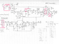
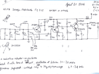
My schematic drawing for the first build of the Desert Ratt 2.

March 8 (morning): Replaced the transistor, no change. Checked voltage again — tried removing various wires implicated in the issue, and found a copper ‘hair’ crossing from the ground plane to an island. Once I removed it, I started to get some fuzz indicating oscillation. Still lots of intermittent noise; soaked the board in alcohol and dried it. This is the last time I’ll cut out islands! There just isn’t enough dependable separation between the islands and the ground plane. Should I start over?

March 8 (afternoon): Popping noise seems to have gone away now that the board has dried fully. And with the evening, I start hearing stations. It chooches!
March 9 (evening): I switch wires for most of the pots as they were wired in backwards (as in loud to the left, quieter to the right). Frequency calibrated after removing a few turns from the main tuning toroid. A is 3.0-6.3 MHz and B is 3.1-7.8 MHz. Very good fidelity and dynamic range. I’m satisfied with this radio’s sound.

Building Radios

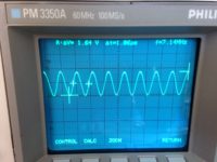
W1FB’s design for a VFO (Variable Frequency Oscillator): output on scope

I’ve not been posting consistently lately. The main reason is that I’ve been indulging my curiosity in radio technology. It started when I wanted to learn more about the wireless systems that I was building into my Arduino projects. The explorations and experimentation into radio have taken over, but I’ve not been able to answer in my own mind where this was taking me, until now.

So I’ve been building and playing with radio-frequency (RF) circuits, starting with oscillators, moving on to amplifiers and then simple radio receivers.

Some history might be helpful: A hundred years ago, when radio was new, experimenters built their own radio gear. The first radio transmitter was a device that made a spark, and a little later, sparks—which splashed energy promiscuously across a wide spectrum of frequencies—were replaced by narrow-frequency signals that could coexist with other signals with a radio that could select (or tune) into one signal and ignore the others. This signal is produced by an oscillator, which vibrates at a frequency of several million times a second.

Low power AM transmitter for test purposes

Wireless signals—whether they be wifi, Bluetooth, FM or your garage door opener—all use oscillators to carry information. So step one in anyone’s search for knowledge in this field is to build an oscillator.

Actually, there’s a step zero: in Canada, the electromagnetic spectrum is considered public property. You just can’t set up a transmitter and spew electric energy in all directions. You need to abide by a set of regulations set by Innovation, Science and Economic Development Canada, and above a certain power level for your transmitter, you may need to obtain a licence. In my case, I have a Basic with Honours amateur radio license VE1LEB, which allows me to experimentally transmit, using commercially-designed equipment, up to 250 watts in certain high-frequency bands. Unless I upgrade my licence to “Advanced”, I’m not allowed to employ a transmitter that I build myself — unless it’s a kit and/or I’m transmitting at a very low level.

Used as a buffer for AD9851 frequency generator

So when I build experimental oscillators, I’m only allowed to run them at very low power so that they can’t be heard more than a few metres from my house.

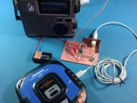
Here’s a practical example from last summer: I wanted to test the performance of a radio that receives signals in the AM broadcast band, between roughly 500-1600 MHz, but in Halifax, Nova Scotia, all of the AM broadcasters have vacated this band in favour of the FM band. So when you turn on an AM radio in Halifax (during the day, at least), you’ll get noise, hiss, static, but nothing intelligible to a human. So I had to build my own little radio station that would modulate an audio signal from a CD player with a carrier wave around 1000 KHz. Tune the radio to around 1000, and you should hear music (but only if the radio is sitting next to the modulator circuit).

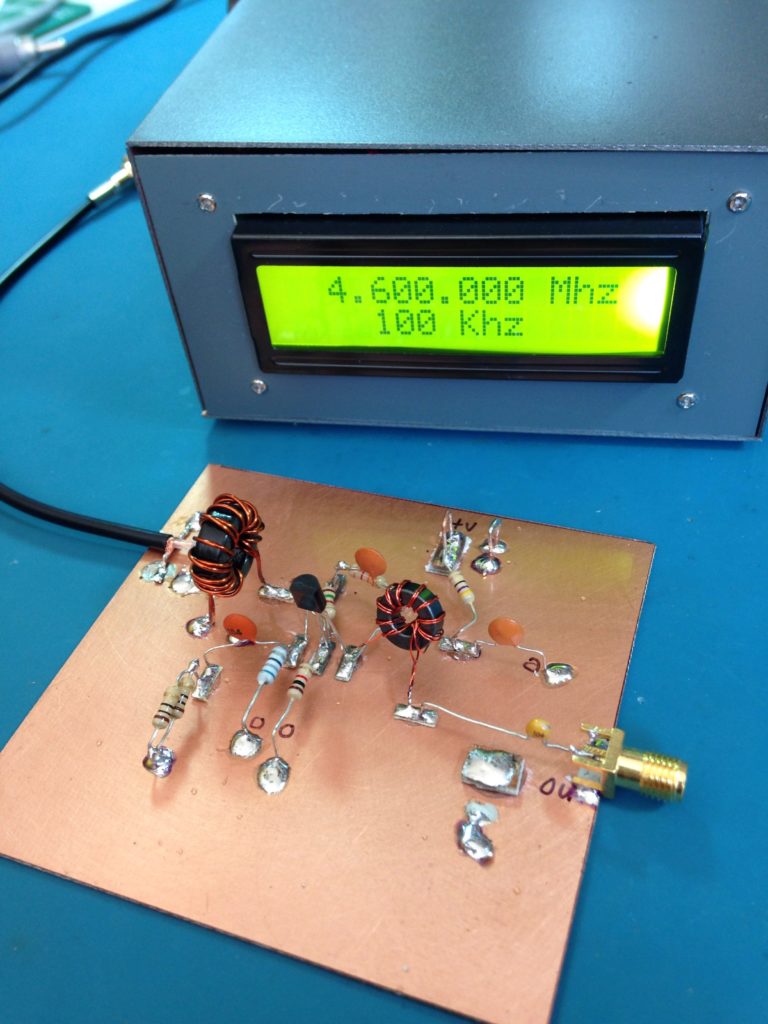
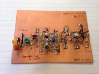
Here’s another example from last Fall: this circuit is from a design by Doug DeMaw W1FB that combines an oscillator with an amplifier. It’s a VFO (variable frequency oscillator) with a buffer amplifier that can be used as a stage in either a transmitter or receiver. The circuit was built on a single-sided PC Board, with islands of copper cut out using a copper engraver’s burin—a tool acquired during my days as a Fine Art Major. The components are soldered onto the islands. The rest of the copper is known as a ‘groundplane’: reserved for connection to zero volts (ground).

Direct conversion receiver

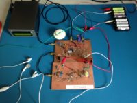
After that, with an increase in confidence, I moved on to building simple radio receivers. The first one used an amplifier design from the book “Crystal Sets to Sideband” by Frank Harris K0IYE. It’s known as a direct conversion receiver, one that’s unusual from most radios we use today because it doesn’t make use of intermediate frequencies to step the signal down from it’s original frequency to audio frequency. The radio is composed of an oscillator an RF board and an AF amplifier.

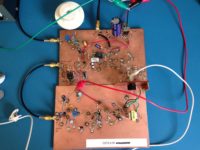
Direct conversion receiver – close up

The radio signal is brought into the receiver via a coax cable gold connector at the top left. This signal is mixed with a sine wave signal at almost the same frequency as the one we want to tune to. By varying the frequency of the oscillator, we can tune into different frequencies, which will be displayed on the frequency generator unit. When these two signals are combined, the difference frequency is the audio from the radio station. This low-level audio is transferred to the lower board with a short coax cable to the audio amplifier, which drives small earbuds for listening. The battery pack at the top right delivers about 12 volts to the radio.

This report gets me caught up to late October 2016. My next post will introduce “regens“. I realize that I haven’t revealed where all this activity is taking me in my design research. It will come in later posts.

73!