Back in January, I had just completed the Fuel Oil Level project and as a “wrap-up,” I posted my design process. In Part II, where I went into more detail about the sensor array and sender unit, I mentioned that the latching hall effect sensors had some peculiarities. Now that the unit has been “in field testing” for about a month and a half, I’ve discovered that, well, it doesn’t work.
More specifically, what does work: the transmitter, the Arduino software, and the receiver all appeared to work satisfactorily. Having done a fair amount of electronics design over thirty years or so, I know well enough that each component needs to be tested in breadboard, then in prototype on the bench, and finally, in the field. In this project, everything was tested, at every stage, several times. But obviously there’s something different about the conditions of the bench tests and the conditions in the field. I think I know the reason—I’m not totally certain—but I’ll explain more in a later post.
A Reed Switch Primer
So. Back to the drawing board for a way to detect the level of the fuel oil tank. I decided to try replacing the hall effect sensors with reed switches. I purchased a pack of 10 small surface-mount reed switches on ebay from Thrify’s Place, and when they arrived I set to work on a new design.

I had played with reed switches before, and I thought I knew enough to proceed with testing a new sensor array. I wanted the new array to use the same form factor as the old one, but I decided that I would separate the sensor from the rest of the electronics. Since my oil tank is indoors, it did not need to be covered-up—I could use rubber bands to hold it close to the float guide and use ribbon cable to run the ten or so wires to the Arduino and transmitter.
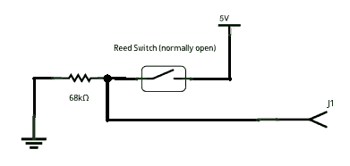
Reed switches are hermetically sealed in a glass enclosure and have two slightly overlapping leads made of ferrous metal. In a normally-open reed switch, the leads close when in the presence of a magnetic field. That’s all there is to it. So I experimented with a single switch to make sure I was understanding how to properly wire it up. In my basic reed switch circuit, J1 is the output that goes to a digital input pin on the Arduino. This is normally held low by a 68k resistor, and when the reed switch closes, it completes a circuit to 5v, which drives the output high.

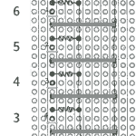
So I set about making eight of these little circuits and soldering them to a veroboard. I attached the reed switches lengthwise along the stripboard strips and staggered them so that the centres of each reed switch would correspond to a different level of the oil tank. In workbench testing I found that the results were erratic. It didn’t seem to make sense, so I rigged up the same arrangement on a breadboard—and I received the same erratic test results. As it was a Saturday afternoon, I decided to take a nap, and once refreshed, go back to school…

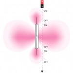
Meder Electronic sells reed switches and they have compiled a very complete set of resources on these devices. I found an excellent paper (PDF) on the myriad ways one can configure a reed switch. The Meder article explained the erratic behaviour of my array: depending on the orientation of the magnet in relation to the reed switch, the switch itself can have several areas where it is sensitive to a magnetic field. I was not aware that the ends of the switch are sensitive in addition to the areas in the centre of the switch.
As the magnet passes by the switch, it may intersect the sensitive area at one end of the switch, closing the contacts. As it moves closer to the switch, it leaves the end sensitive area (causing the contacts to open), then it enters the main side sensitive area, closing the contacts again. As it passes, the magnet can cause the switch to open and close three times.
A Second Design

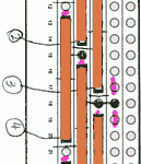
Armed with my new knowledge, I designed a new sensor array, this time with the reed switches oriented horizontally. The reed switches, represented in brown, are soldered onto lines 8 and 15 of the stripboard, and the eight pink lines indicate cuts in the strip. My intention is to mount the array so that the magnet moves across the right ends of each reed switch. This way the magnetic flux would act only once on each switch. A test with the array held manually onto the oil level gauge was successful, but I think that the placement of the array in relation to the magnet on the gauge is going to be the tricky thing.