A whimsical project called “Shy Dildo”: the object is a ‘personal massager’ that vibrates when left alone but stops when it is touched…
Of all the projects so far, the Shy Dildo was the simplest in concept—a vibrator that runs until it is touched—but the most difficult to actually design and build. I had actually assembled three completely different circuits, using four types of sensors.
They were, as I built them:
- Passive Infra-Red (PIR) sensor
- Infra-red LED emitter/receiver pair
- Ultrasonic Rangefinder
- Capacitive sensor
And once I had settled on capacitive sensing as the method for the project, several breadboarded versions were built. Even then, I had not covered all the technical issues, and without the generous advice of two engineers from Azoteq, the project would have been abandoned.
Passive Infrared (PIR) Design
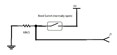
The PIR is a motion detector that is used in security systems. It’s inexpensive, and can detect movement of warm body objects from several metres away. An Arduino controller handles the logic and drives the vibrator motor.But once I had breadboarded this, I realized that I didn’t want to detect motion, I needed to detect proximity (or contact).
Infra-red LED Emitter/receiver Pair

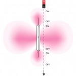
This method uses an infrared switch: this is a single component with four wires. Two wires drive an infrared LED and the other two wires are connected to an infrared detector (a reverse-biased IR LED). An Arduino controller handles the logic and drives the vibrator motor. This arrangement worked well, but it was too local: the vibrator is 15cm in length, but the infrared switch works only about 4cm around it, necessitating several IR detectors to be fitted along the length of the vibrator. I also wanted the sensors to be undetectable, so this method was rejected.
Ultrasonic Rangefinder

Ultrasonic rangefinders are common in robotic systems. They silently—at least for humans—repeatedly ‘ping’ into the air, using high frequency sound waves. A high-frequency microphone detects each ping and a micro-controller determines the distance from the target. The Arduino also drives the vibrator motor. This worked well, from about 20cm (far) to 2cm (close), but also suffered from the same drawbacks as the Infra-red LED switch.
Capacitive Sensor
I played with capacitive sensors years ago: Don Lancaster, in his classic “CMOS Cookbook”, discusses how the typically high-impedance inputs are so sensitive to changes in electromagnetic potential, that if you leave inputs hanging, they can pick up these changes and change digital states. The book contains several designs for touch and proximity sensors and switches. These methods are, however, less than dependable.
More “professional” approaches (does an art project that includes a dildo qualify?) to the capacitive sensing problem are available in the form of capacitive-sensing integrated circuits. Several are available: Futurlec offers the Quantum QT110, QT113 and QT118, but these have been unavailable for at least a year, presumably because Atmel has acquired Quantum, and Futurlec only sells Atmel microcontroller chips. Sparkfun sells one made by Analog Devices.
Sure Electronics, however, sells a set of five nifty IQS127D chips that are made by Azoteq, a South Africa-based company. The IQS127 chips from Sure Electronics are surface-mount, so Sure has helpfully included five SMD-to-.1 inch adapter boards. Because they are so small, surface mount devices require magnifying glasses, lots of light and a steady hand. Some people are intimidated by them but I enjoy the challenge. There are several good how-to videos on soldering surface mount chips.
The IQS127 is a magical chip [PDF]. It can be ‘tuned’ through software, but at its most basic, it has two inputs: pin one for proximity and pin 3 for touch sensing. Sure’s brief description of the chip:
IQS127D is a fully integrated capacitive sensor having dual outputs- Physical Contact (Touch) and Proximity output. It can operate with a minimum of 1 external component and project a touch pad through almost any dielectric. This device features an internal system regulator, ensuring class leading proximity sensitivity and stability. It is suitable for various dielectric overlays. In addition, a SOT23-6 converter board is provided for each chip so that you can break out the pins of the chip for better use in your projects.
95% of my experimentation on this chip was in its proximity sensing mode, but erratic behaviour forced me at the last minute (when I was testing the performance of my assembled and soldered final prototype board) to switch to touch sensing. More on that later.
The Vibrator
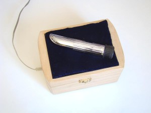
 This is where I lucked out: I ordered an inexpensive vibrator at DealExtreme, in their “Naughty Products” section. I was looking for a simple gold or chrome coated vibrator… not an easy task on a site that has hundreds of “personal body massagers” of different designs, some true to life and others simply ridiculous, like the Santa Claus massager for $5.30 (free shipping!). However, I did find the needle in the haystack, and it arrived in working order. Not only that, but the chrome coating on the vibrator was conductive. Out of the hundreds of vibrators made in the electronics factories of Guangzhou, I found the one that conducts current! This meant that I could attach the sense wire to the outside of the vibrator and the entire surface could be used as a sensing plate.
Here’s a PDF of the Shy Dildo Electrical Connection Detail.
The Two Power Supply Problem
Since the IQS127D chip would handle the decision of when to turn on and off the vibrator motor, I was not required to include an Atmel microcontroller, which would simplify things somewhat. On the other hand, I had to deliver 1.5 volts to the motor and 5 volts to the IQS127D. The motor requires about 250 mA while running, and probably twice that to get from a full stop to full rotational speed. The IQS127D uses a few milliamperes, not enough to worry about.

My first design took a 12v DC input and routed it to two LM317 adjustable voltage regulators. One was configured to output 3v and the other to output 1.4v. The 3-volt supply powered the IQS127D and the 1.4-volt supply powered a transistor driving the motor. The transistor and the motor used reverse-biased diodes across them to eliminate inductive spikes that arise at motor startup. By the way, this web page is an excellent guide to the use of discrete transistors in common circuits. I (temporarily) abandoned the two regulator approach because the motor and the IQS127D seemed to interact in what seemed like a feedback loop that cycled every second or so.

My second design idea was a more elegant solution to the problem: the LM317 regulator cuts down voltage in a brute-force manner; the excess power is released as heat, requiring a heat sink if you are driving large loads. Instead, I would use a 555 timer chip to create a rudimentary switching power supply, making much more efficient use of the DC power available to me.
Using this circuit, a 555 timer chip was configured to output at 150 Hz with a 30% duty load sufficient to cause my multimeter voltage display to read 1.4 volts. This waveform would be fed into a NAND logic gate with the signal from the IQS127D, which would give me 1.4 volts when the IQS127D told me it needed it.

Unfortunately, the feedback loop problems continued with this circuit. My engineering skills were inadequate to deal with the issues, so I sent a drawing of my circuit to Azoteq. The next day, I received a reply from Ross de Jager, which included an amended schematic. Ross noticed that
- there were no electromagnetic noise suppression capacitors fitted to the motor
- at the power supply, the capacitance at the voltage regulator entry point appears to be too small, which may cause a dip in the power supply voltage
I made the changes he suggested, but the performance was still not what I had hoped. I decided to abandon the 555 timer chip, go back to the two-regulator idea and try using a simple small relay to switch the motor on and off.
After about a month (during an unusually wet and dreary month of June here in Nova Scotia), I had another round of assistance from Ross at Azoteq. I was not unhappy with things at that point, because I’m not an engineer and I’m also more interested in getting a point across and amusing people.
In the video, the vibrator works until it is touched (actually actuator proximity is around 5mm from the surface of the device), but there are two aspects of its performance which troubled me:
- When getting close to the device, it cycled on and off. I wondered if this is to be expected? I also noticed that it seems to do this more under inductive load than under non-inductive load.
- Sometimes when the device was touched, it turned off, then turned back on almost immediately. Other times, it stayed off for ~20 seconds. I wondered if this was the expected behaviour?
Ross replied almost immediately:
An important point to remember here is, that if instability is present in the sense plate or environment, it will manifest here first when trying to detect proximity, as the IC is much more sensitive to current sample variations, especially if you have not programmed the IC to meet your application requirements. Floating metal could be a big problem and causes enough cyclic current sample variations to detect false proximity. In your case instability can be counteracted by either:
- Reducing proximity sensitivity threshold of the IC (Requires programming of the IC with the Azoteq CT200 configuration Tool)
- Ensuring that metal parts are gounded or used as a sense electrode, to prevent floating metal.
- Switch to the touch detection output of the IC (connect your motor activation line to PIN 1 of the IC, instead of PIN3)
From your viewpoint, I believe that you do not want to get into the programming details or configuration of the IC, so in your case I recommend that you opt for the third option, since in your application you want to detect a detect a stable touch, rather than proximity…
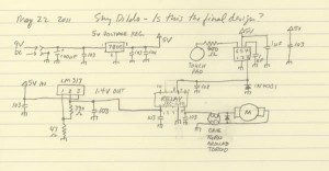
Ross helpfully followed up with a very helpful discussion on the concept of potentials and ground and pipe grounds and floating metal. I should reiterate that the IQS127D is not to blame here; I’m delighted with its performance. The difficulties that I encountered happened because I’m not an engineer. I’m just a ‘dopey artist’ (as I once heard my old teacher painter David Wright say). I took Ross’ advice about switching from proximity sensing to contact sensing. I made some final adjustments to the circuit, and it’s now finished:
Schematic for Shy Dildo v 2.3 [PDF] and source files.
Shy Dildo by Michael B LeBlanc is licensed under a Creative Commons Attribution-Noncommercial-Share Alike 2.5 Canada License.
Contact the writer for permissions beyond the scope of this license.
