Tag Archives: radio

Desert Ratt 2 (Second Build)

I’m embarrassed that it’s taken me this long to get this post out. It’s currently nearing the end of August, and I started this project in mid-March. It was really wrapped up in late April, but I had to wait for parts to come from Asia for the enclosure, and they didn’t arrive until June, and then the summer arrived. Oh well.

I benefited from the experience of the first build: I got a good sense of how much space the individual components required, and how to best position the sub-assemblies relative to each other. I had also received my Prusa i3 Mk 2 3D printer with the intention of making boxes for these projects. My thinking evolved from making a presentable box for the radio to thinking about how I actually used the radio, and how to position the controls for most comfort and efficiency.


Here’s my design journal:
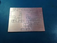
March 14, 2017:
PC Board
PC board before soldering

This build will use mainly surface mount components on a board which is half the size of the first one. It measures 100x75mm. The islands that I cut in the copper are sized for surface mount resistors and capacitors. Since most of my experimentation was on the first build, I had confidence to concentrate the components. Radios that have closer connections between components are also usually better performers.
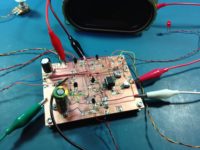
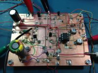
March 15:
Assembled board
Parts are now soldered on.
Assembled board
Now ready for power up. And thankfully, no magic smoke has escaped!

A storm took down the antenna wire attached to the front of the house last night. The hemp string attaching it to the tree gave way. The wire (from a CAT5 cable) is very strong and has lasted two years without breaking. Environment Canada recorded wind gusts up to 109 km/h which is approaching minor hurricane speed. Main vertical antenna in the back yard is unaffected.

Most of the SMT components are now soldered down.

March 21: 

Completed most of the components and peripherals. After a couple of minor revisions, this radio now works — even better than the first! Although band conditions are very bad (minor storm and geomagnetic instability), I’m still able to receive a couple of stations over the noise and fading in and out. Fidelity seems much better on this radio.

Geomagnetic Conditions
Reception is Poor Poor Poor Poor Poor Poor Poor Poor


Enclosure

”It’s not just a box!“

If you’ve ever spent any time in front of a regenerative radio, it doesn’t take long to understand why, despite the excellent sound, dynamic range and overall performance of the design, most radios that work in the medium and high frequency broadcast and shortwave bands are not regens. They’re use different designs that allow the user to tune to a station and then leave it. One big disadvantage of regens is the fact that you have to constantly and carefully adjust the feedback and tuning to get the best reception. There’s a challenge to pulling out a distant signal using one of these radios, and you need two hands to do it.
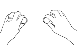
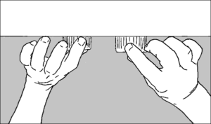
radio-ergonomics-front
Position of hands on radio dials, from the front
radio-ergonomics-top
Position of hands, from top

That brings up an ergonomic issue: conventional radios are boxes with a speaker and control widgets facing outward from the front. This arrangement serves the average listener reasonably well; the radio is tuned once or twice in an hour and most of the time the listener is not touching the radio at all, so it really doesn’t matter where the controls are.

However, because regenerative radios require constant attention, I found that my hands and arms started getting a little uncomfortable after 15 minutes or so of constant adjustment of the dials. After a few days of using it and thinking about it, I realized that if the controls were on the front, an operator’s hand/wrist/arm had to be contorted into an unnatural and eventually uncomfortable position.

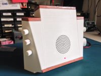
So my next question was “if the radio box resulted in discomfort, what would be more comfortable?” I surmised that if I were able to turn the rotary controls on an angle so that they don’t face directly at the user, but rather faced perpendicular to the user’s forearm, it would result in a more natural control position. I also thought that the front of the radio should be angled upwards slightly, since the radio will be on a desktop: on a ‘box’ radio that is positioned on a desk in front of a user, the speaker is aimed at the listener’s upper chest. The speaker should be pointed directly at the listener’s head, since that’s where her ears are!
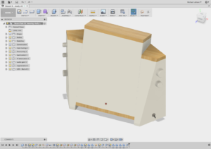
Screen Shot of Design in Fusion 360

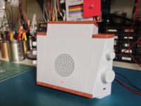
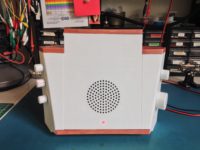
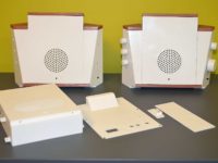
Here’s the design as it looked using Fusion 360 in the middle of my development cycle. The design consists of a main centre unit, which holds the circuit board and the speaker, and two side pieces which are bolted to the main cabinet and which hold the user interface items. The enclosure is meant to be entirely 3D printed. The wood too!


Adding a Relay for Band Changing

March 23:
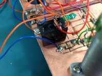
Adding a band switch relay (closeup)

The radio is capable of tuning to two bands: from around 6.5-8MHz and from 9-12MHz. This is done by flipping a toggle switch. The switch itself is some distance from the circuit board, which means that the long wires to and from the switch are likely to adversely affect the circuit. After playing with it al fresco, I made one modification to reduce the length of wire to and from the circuit: I replaced the long leads (20cm) for the band switch with much shorter leads (4cm) to an HK23F-DC12V relay. The relay is actuated by the band switch on the far side of the radio, but the RF signals that are re-routed in the band switch are much shorter. This probably increases Q (makes for sharper tuning) and lowers the total capacitance of the band switch circuit to the values defined by the two small 10pF and 47pF caps.
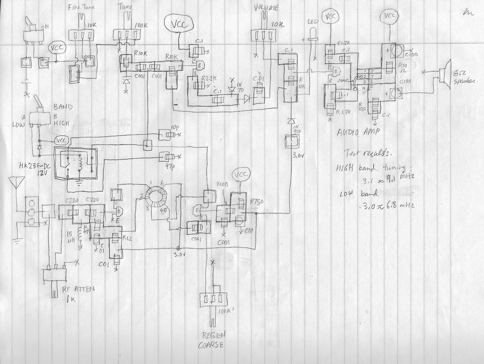
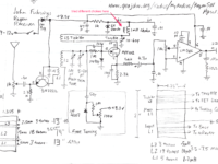
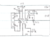
Here’s my final working schematic:
Desert Ratt 2 Final drawing
Desert Ratt 2 Final Drawing


Designing the Cabinet for Production

By mid-April, I had printed a draft enclosure to see if it everything would fit together.
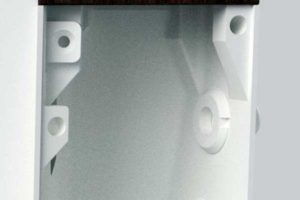
No 90° overhangs
No 90° overhangs that are unprintable

Printing in 3D has its own opportunities and limitations. Because it prints up from the bed layer by layer, certain structures such as overhangs longer than about 1cm are not possible without first defining support structures that can be removed after the print is completed. However, careful design can reduce and sometimes even eliminate support material structures. The Prusa i3 Mk2 is capable of printing 45° overhangs. In the case of this enclosure, very few supports were used; if there were overhangs, such as the surfaces that hold the threaded brass inserts, these were extended to between 30 and 40°, as you can see in the detail of this rendering.

Desert Ratt 2, Draft Enclosure April 16:
  • Centre: need some strengthening fixed
  • Circuit board: use 2.0 mm holes, 4mm deep, add 1.5mm washers fixed
  • Band Switch: placement guides not large enough: block is 15 x 31 mm fixed
  • [Small, medium knobs need at least 5.9 mm dia -they appear to be 5.8mm – is this due to draft mode printing?]
  • Knobs need to have longer skirts – try 4mm fixed
  • add dial dots on main tuning fixed
  • add diode in front of VCC not done.
  • add headphone jack on back? not done.
  • swap out pots for new ones fixed
  • Speaker magnet collides with centre back – replaced

This last point was a surprise; although I thought I had measured everything, even to the point of modelling-in the components, I didn’t model the speaker correctly and the test fit quickly showed that the back panel wouldn’t fit with this large speaker. So it just goes to show: you can have fantastic design software but there’s just no replacement for printing one out and doing a test fit.

Edit: Actually, I printed two full copies in the 0.20 mm “normal” detail setting before printing the final using the 0.15mm “optimal” detail.

Here’s a Fusion 360 render of the back:
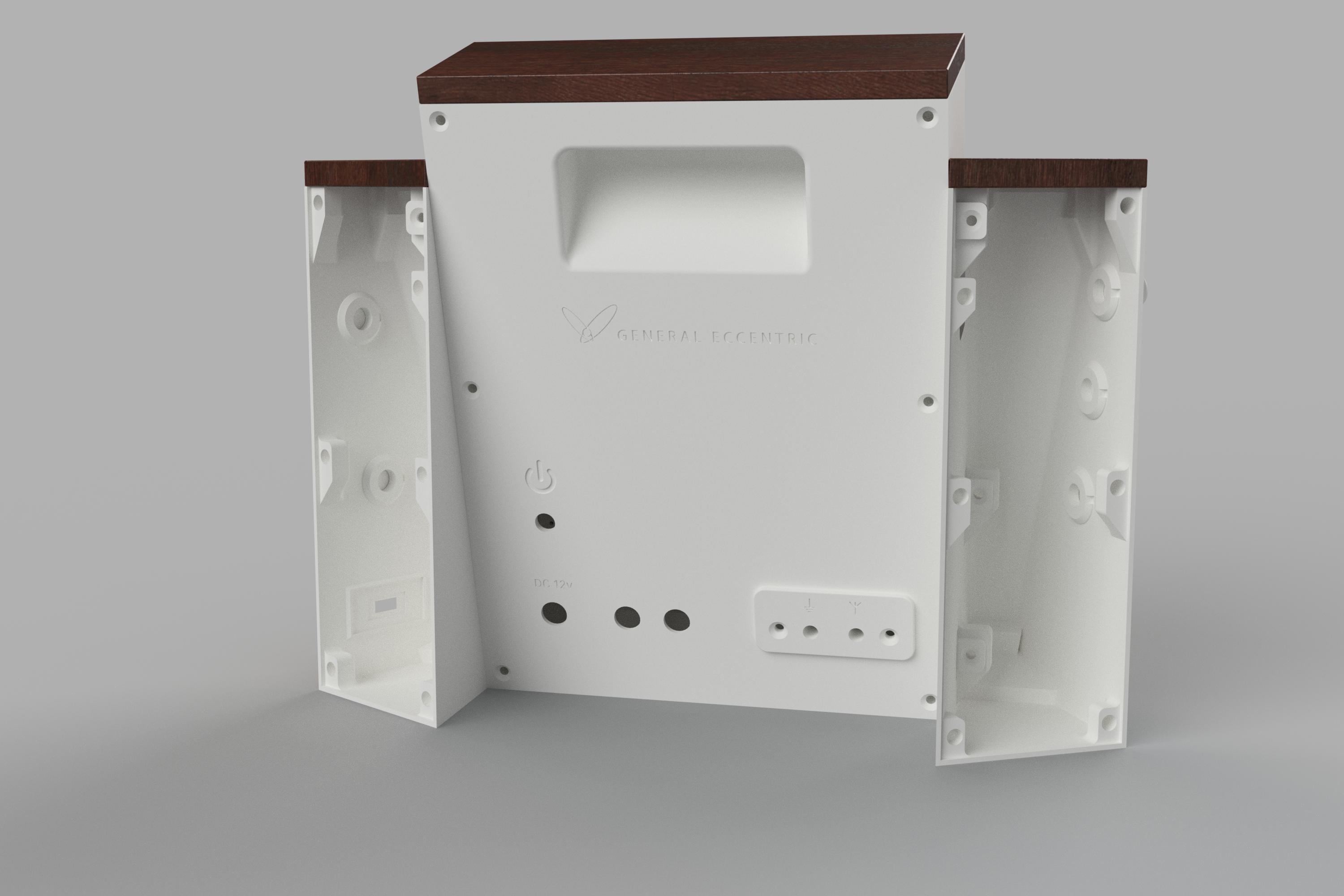
Back view render
Back view render

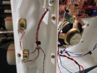
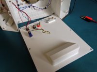
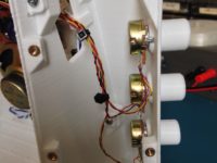
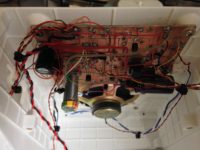
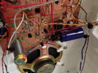
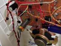
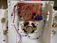
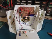
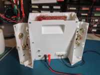
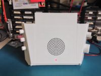
And here are a couple of photos of the actual test fit:
Desert Ratt 2, Draft Enclosure April 18
  • Centre re-designed with web strengtheners
  • replaced old grille with Dieter Rams 1973 grille: “steal from the best”
  • added Dial Dots around the Main Tune pot on the right UI
  • vertical web strengtheners will not print in Draft mode, printed in normal mode
  • fashioned clips and mounted new circular speaker
  • swapped out old potentiometers
  • stained wood pieces
  • added “UI clips” on the cable holes to bring the shells closer together
  • listened in the evening many strong stations… great sound! It’s amazing how much better a speaker can sound when you put it in a box.
Desert Ratt 2, Draft Enclosure April 19
  • tried listening in morning: unable to tune. Much back and forth. Problem seemed to be located in Regen circuitry & pot. Replaced transistor closest to Regen pot. Finally, replaced the Regen pot. Pot went bad!
  • bundled cables with nylon ties
  • urethaned wood

The 3D printed wood pieces were printed from Spool3D “light brown wood” PLA filament. Spool3D is a Canadian company and I buy all my filament from them. My only complaint is that I’ve never been able to get a proper answer from them on what Munsell values they use for their coloured filaments.
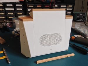
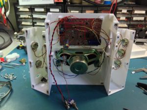
Test Fit (front)
Test Fit (back)
Test Fit (back)

The wood colour is, as the name suggests, “light brown”, and I was able to stain it (after sanding) with three coats and then lightly give it one coat of urethane. The rest of the cabinet used Spool3D White PLA.

The three sections are screwed together using M3 screws into brass inserts. The inserts are placed on the end of a hot soldering iron, and after about 5 seconds you can press them into place in the plastic and once they cool, they are bonded into the plastic. I found this technique on Youtube.

One last change was the speaker and speaker grille. My initial idea for the grille was to make holes that mimic the dot-dash of morse code. When I transitioned to a smaller round speaker, I stole Dieter Ram’s TP1 record player grille design. In the end I made one final further refinement by making the grille slightly convex.

The final enclosure was printed in “natural” PLA. This was a mistake, because natural PLA is slightly translucent, and I liked the white material better. I resorted to sanding, priming and spray painting the final print—a lot of work that could have been avoided had I printed in white. While PLA is great to print with, it’s difficult to sand and otherwise work with. And because PLA has a melting point of 60° C, I can’t place it in hot environments like a closed-up car in the summer time.

One last observation: it’s amazing how much better a radio sounds when you place the speaker in an enclosure. Or a box.

Here’s a short video of the radio. Unfortunately it was done on an evening with a K index of 4 (unstable geomagnetic conditions). More photos below the video.
 

Desert Ratt 2 (First Build)

Paul Harden NA5N designed the Desert Ratt shortwave regen receiver in the mid-1990’s. It’s a popular radio for builders, and my choice was due to the excellent documentation and the fact that it was designed to tune using varactor diodes, rather than metal fin variable capacitors (that were used in the original Desert Ratt).

Here’s my construction journal:

March 4: Started with the LM386 and the transistor preamp, could not get it to chooch. Reverted to the breadboard. AA7EE has pin 7 unconnected. There’s a principle that you should start with the audio amp and work backwards; this doesn’t work as expected because (as I found out), I needed to bias the base of the transistor on the breadboard before I could get output.
March 6: Soldered a socket and completed the audio amp portion of the circuit. Hoping that it will work as advertised, now that everything is soldered in, once again.
March 7: Completed soldering all components. Result is motorboating. Check AA7EE: he switches pins 2 and 3 on the LM386, which I do, and it’s a relief. However, still no output from the radio. There should be around 2v on the base of the top left transistor, but it’s at ground.
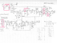
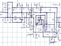
My schematic drawing for the first build of the Desert Ratt 2.

March 8 (morning): Replaced the transistor, no change. Checked voltage again — tried removing various wires implicated in the issue, and found a copper ‘hair’ crossing from the ground plane to an island. Once I removed it, I started to get some fuzz indicating oscillation. Still lots of intermittent noise; soaked the board in alcohol and dried it. This is the last time I’ll cut out islands! There just isn’t enough dependable separation between the islands and the ground plane. Should I start over?

March 8 (afternoon): Popping noise seems to have gone away now that the board has dried fully. And with the evening, I start hearing stations. It chooches!
March 9 (evening): I switch wires for most of the pots as they were wired in backwards (as in loud to the left, quieter to the right). Frequency calibrated after removing a few turns from the main tuning toroid. A is 3.0-6.3 MHz and B is 3.1-7.8 MHz. Very good fidelity and dynamic range. I’m satisfied with this radio’s sound.

Fun with Regenerative Receivers

Hackaday recently had a post called “Everyone Should Build at Least One Regenerative Receiver“. These are relatively simple radios to build and they can receive any type of modulation, from AM to Single Sideband, to FM. Although the regen is one of the oldest receiver designs, it’s still widely used in garage door openers, walkie-talkies and wireless “internet of things” devices.

Over the past year or so, I’ve taken the “at least one” part of the title literally. Last year I built several regens, some successful, some not:

John Fuhring’s Regen Receiver – April–October 2016

John Fuhring has an extensive and entertaining account of his attempts at building a Charles Kitchin “Scout Beginner’s Receiver” regen kit. Because he was so forthcoming about his ups and downs in his regen saga, I decided that I’d try following in his footsteps for my first scratch-built regen.

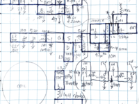
My plan was to use a variation of the manhattan style of component placement, by cutting-out spaces from a grid of squares on the copper surface of the pc, as I did with the oscillator/amplifier project described in the previous post.

The radio tuned from 6.4 – 8.0 MHz. Although successful, it had poor selectivity (radio stations on top of each other), it had a hum from the power supply that was alleviated by substituting a battery, and the LM386 audio amplifier was susceptible to troublesome ‘motorboating’. I disassembled this radio in December 2016.


Ray Ring’s High Performance Regenerative Radio – October 2016

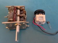
Tuning Devices compared
Tuning Devices compared. From left to right, an air variable capacitor, a polyvaricon, and a varactor.

What attracted me to this circuit were the words “high performance” (although as I’ve discovered, a large percentage of designs promote themselves this way, but in my experience “high performance” may not fully apply) and the fact that the tuning mechanism can be easily adapted to employ a solid state “varactor” rather than the old-school and increasingly hard to find “air variable capacitor”. I’ve managed to collect a few air variables over the past couple of years. They have good selectivity but the dial travel is only about 180°, so they are difficult to tune unless you build a string pulley dial (used in most table radios back in the day) or use a vernier reduction gear mechanism (expensive and also hard to find).

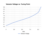
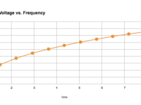
Varactor performance graph
Some experimentation shows that the tuning is fairly linear from 5 – 8 volts.

There are two alternatives to the air variable: the first is the “polyvaricon”, which is used in most clock radios and portable transistor radios. It doesn’t have as good selectivity as an air variable, and it’s also difficult to tune. The other is the “varactor”: this is a special diode which changes its capacitance based on the amount of voltage that is used to bias it. A varactor is tuned with a potentiometer—standard pots have a travel of around 270°, which is better than variable capacitors—and you can also use an inexpensive ten turn pot which can tune into even the narrowest of signals.

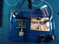
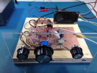
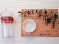
RRing Regen Build
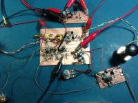
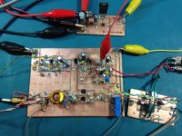
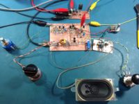
The low pass filter is at the top of the photo to the left of the speaker. Also on a separate board in the centre right is the LM386 audio amp circuit.

My initial build of Ring’s circuit used a polyvaricon, then two in parallel but the result was unstable. I tried different varactors. I also struggled with local FM broadcast interference: to combat the breakthrough, I built a 7-pole Butterworth low pass filter. I discovered that the hookup wire in the RF part of the radio was also picking up FM broadcast harmonics, so I replaced the wires to and from the low pass filter with RG174 coax, and that solved the problem. As you can see, I used the manhattan style construction technique.

After much experimentation, I settled on a BB112 varactor which the data sheet says goes from 470pF at 1v down to 20pF at 8v. For reasons that I can’t remember, I set the voltage/tuning range of the radio from 4.75 – 8.5v, which gave me an effective tuning range at one point from 5.0 – 8.2 MHz. I then changed from a small commercial wirewound 11.5 µH inductor to a 5µH hand-wound T50-6 toroid inductor. The radio now tunes from 7.8 – 13.2 MHz.


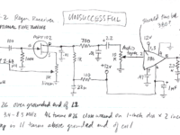
W1FB Doug DeMaw’s Two-stage Regen from his Design Notebook – Unsuccessful

From November 2016, an even simpler design: this one came from the “W1FB Design Notebook”, figure 5-2. The circuit uses a customary Armstrong tapped coil with one Field Effect Transistor (effectively replacing Armstrong’s original vacuum tube). For this build, I used the same technique as the John Fuhring regen above, rather than using copper islands/manhattan construction for the previous radio.

Unfortunately, I could not get the radio to oscillate. Looking back on it, there may have been several reasons for this:

  1. the coil was too close to the copper groundplane
  2. there may have been some solder resin remaining on the board; resin can conduct
  3. it’s possible that I got the windings of the coil backwards

WBR Regen Receivers

WBR receiver - AA7EE's design
WBR receiver – AA7EE’s design

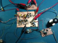
In late December, I built a wheatstone bridge regen using AA7EE’s circuit. Although it did work, performance was disappointing.

I disassembled it shortly thereafter.

The WBR idea remained interesting to me. I found an article from QST August 2001 called “The WBR Receiver” by Dan Wissell, N1BYT. I used his design for my next radio. My notes:

Dec 28 2016
I had some difficulties building this. My first board was deaf—I think because I had mis-wired the connection from the final audio transistor to the LM386.
I made a new board and moved all the components over. The second board was milled using the Dremel stand with a milling table.
The second board, with two 10-turn pots (one for Regeneration and the other for Tuning) seems to work well, and tunes from 8.845 – 9.770 MHz.
Dec 29
  • the pot turn shafts are slightly wider than the knobs that I have. I experimented by using a cutting disk to cut a slot down the middle. Heats the pot up, but seems to do no lasting damage. Also tried just grinding down around the circumference, which seems a better solution.
  • took one turn off each end of the main inductor.
  • the trimpot controlling the lower tuning voltage limit was not wired in properly. Adjusted to bottom out around 1 volt.
  • radio now tunes from 9.450 – 10.070 MHz. Have not yet heard WWV.
Dec 31
  • completed breadboarding: mounted boards and pots, replaced connecting wires with coax where desirable
  • reception seems stronger: however, AM and SSB signals seem to have a tremolo
  • radio now tunes from 9.410 – 10.010 MHz. Have heard WWV!

Jan 3, 2017

AN IDEA: replace the 8v regulator with a 5v regulator, and add a servo motor/Arduino to indicate frequency via voltage level.