Category Archives: Amateur Radio

DC40 Receiver

In the late winter of 2018-19, I decided to build a receiver that would provide a performance improvement to the regen I built a couple of years ago. I wanted the radio to receive AM and SSB signals between 160m and 20m (1.8-14.5 MHz).

Another regen seemed to be out of the question; although regens are very sensitive, they have other drawbacks: they’re difficult to tune, and once tuned, the configuration needs to be changed often to prevent howls of oscillation and other audio problems.

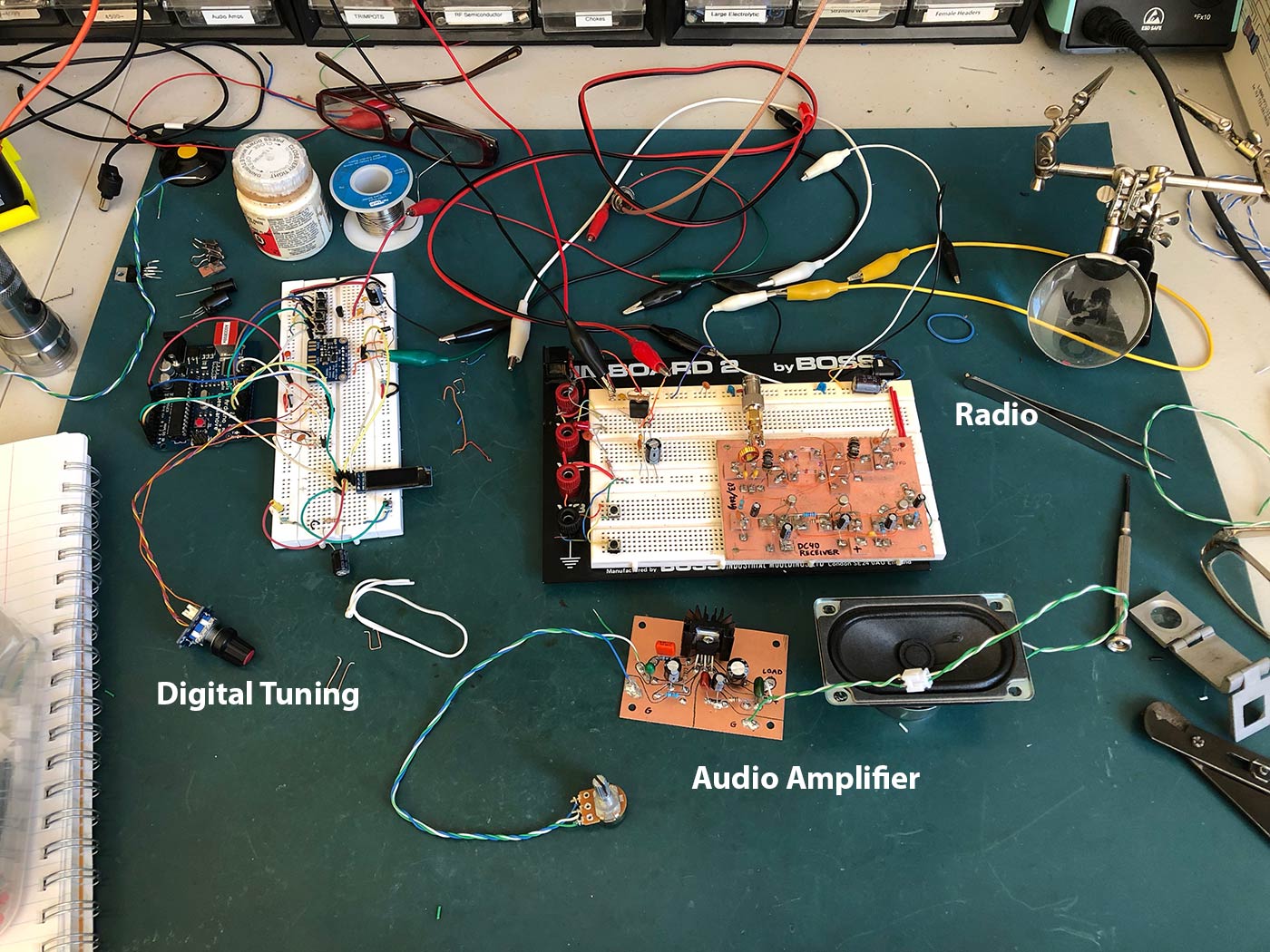
It made sense to me that the next step in my radio-building self-instruction should be a ‘direct conversion’ receiver. DC radios have an oscillator running at the same frequency as the signal you’re trying to receive. This oscillating wave gets combined with the signal in a double-balanced mixer. The mixer converts the high-frequency signal down to audio frequency, where it can be amplified using several audio amp stages. It’s a very simple configuration, and the result is a very clean sound.

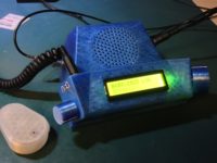
The DC radio can also be fitted with a frequency display, which is in this case is an Arduino that controls an SI5351 oscillator at the frequency I want to listen to, and a digital display that shows the frequency I’m tuned to.

Design

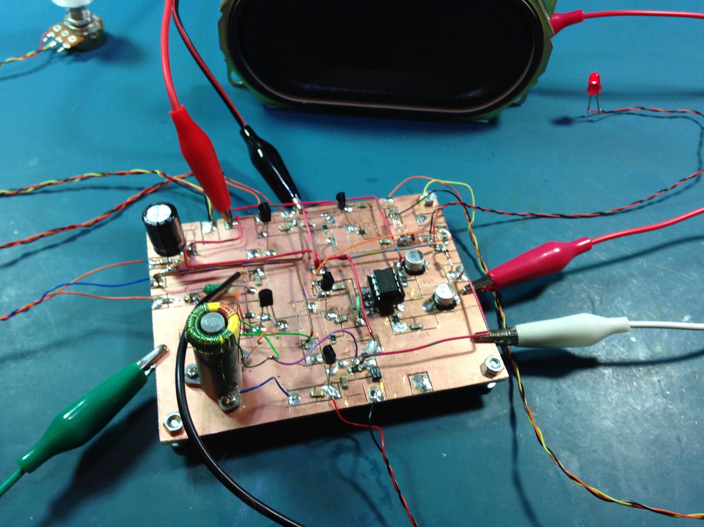
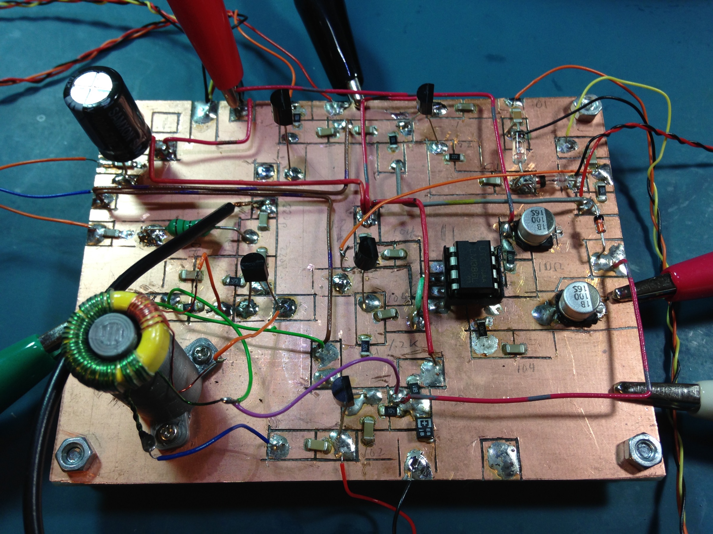
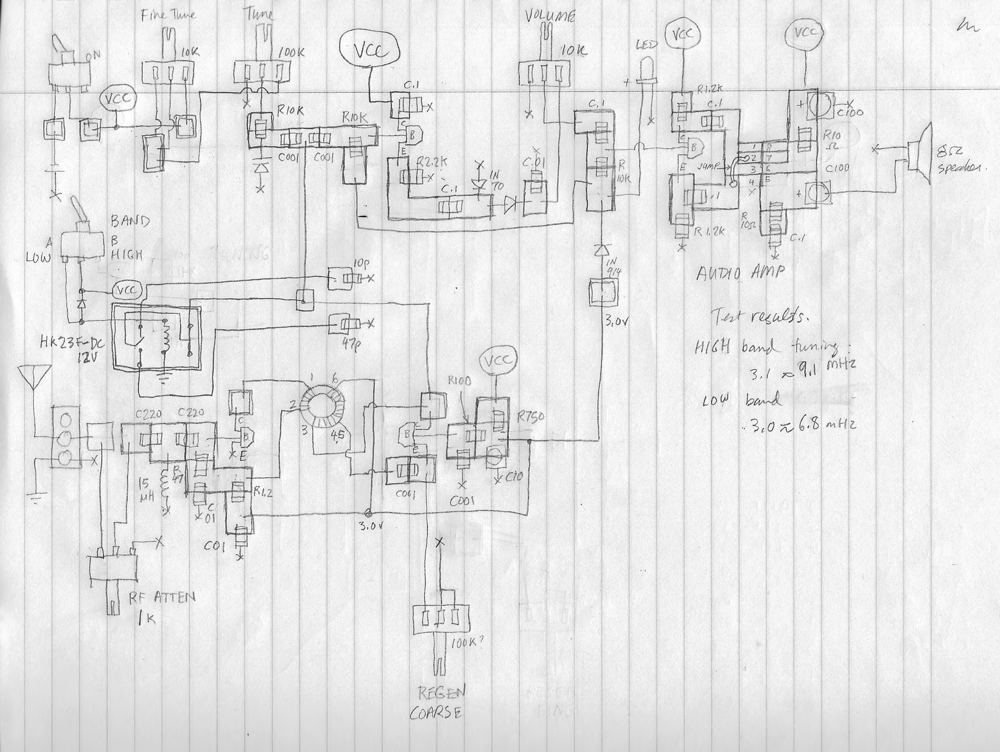
The basic design comes from Farhan VU2ESE, with modifications by Ryan Flowers. I used a different audio amplifier than the ones specified in the original plans. I tried an LM381 preamp and an LM386 but was unhappy with the results. The amplified audio coming out of the LM386 was barely enough to power a speaker and could only be used with headphones. I tried several different audio amplifiers and finally settled on the TDA2003A.

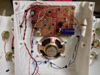
I faced difficulty with hum and there was a tendency for the audio amp to self-oscillate. I added a power line filter, which helped a little, but the best results seem to be to use battery power. Self-oscillation is still somewhat of an issue with the TDA2003 at max volume. You can see from the schematic that I tried to gather 0v (ground) for both the digital and audio sections to a common point, which should help in reducing hum and other problems.

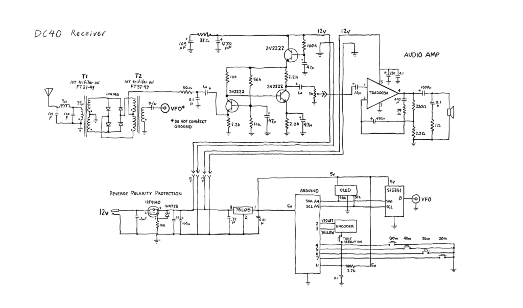
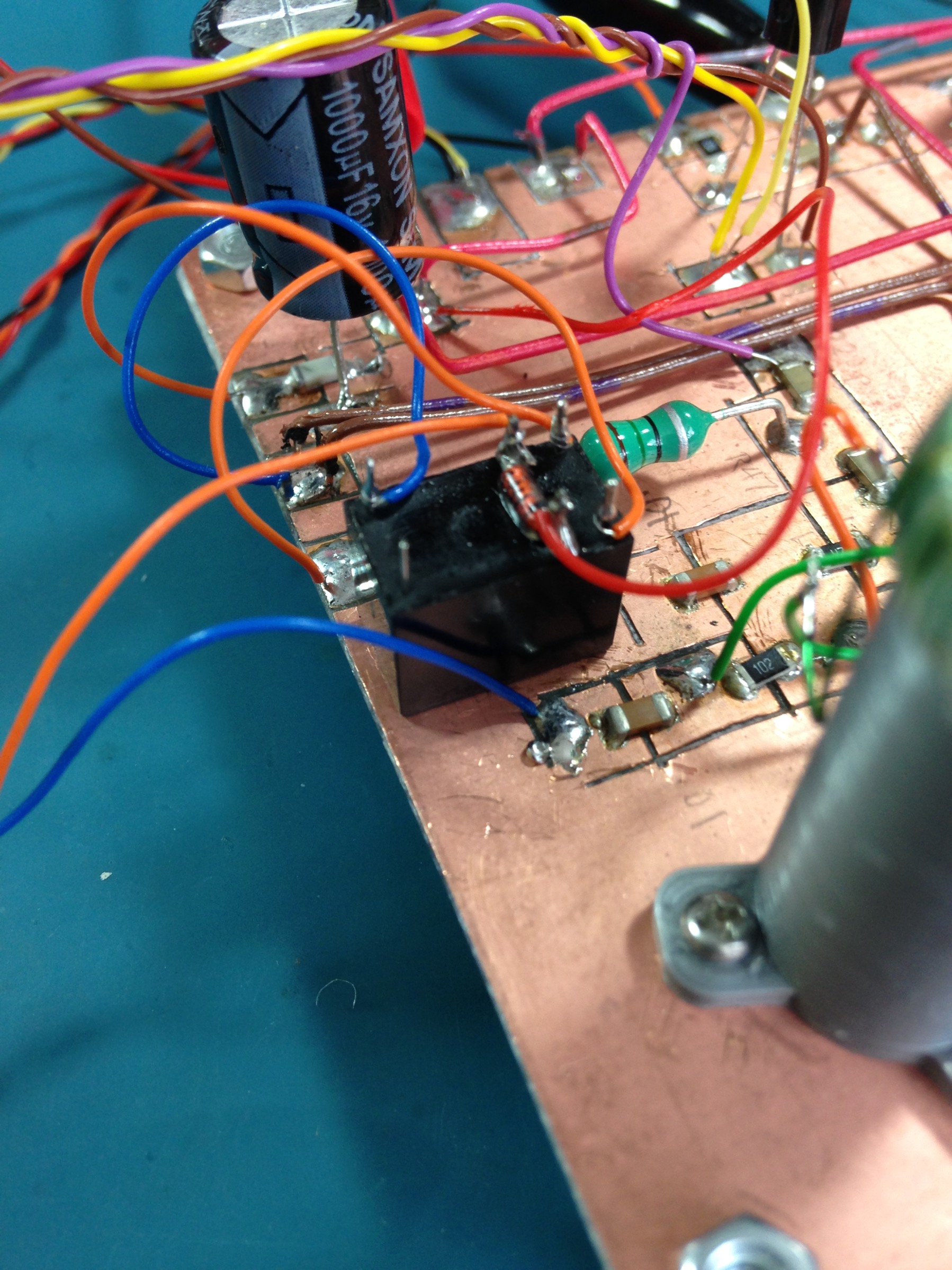
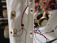
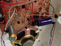
This was the first opportunity I had to experiment with homebrewed double-balanced mixers. I used four closely-matched germanium diodes for the diode ring.

Another first for me: a reverse polarity protection circuit—using an IRF9540 P-channel MOSFET—is placed between the +13v power socket and the rest of the radio. It delivers full power with no voltage drop.

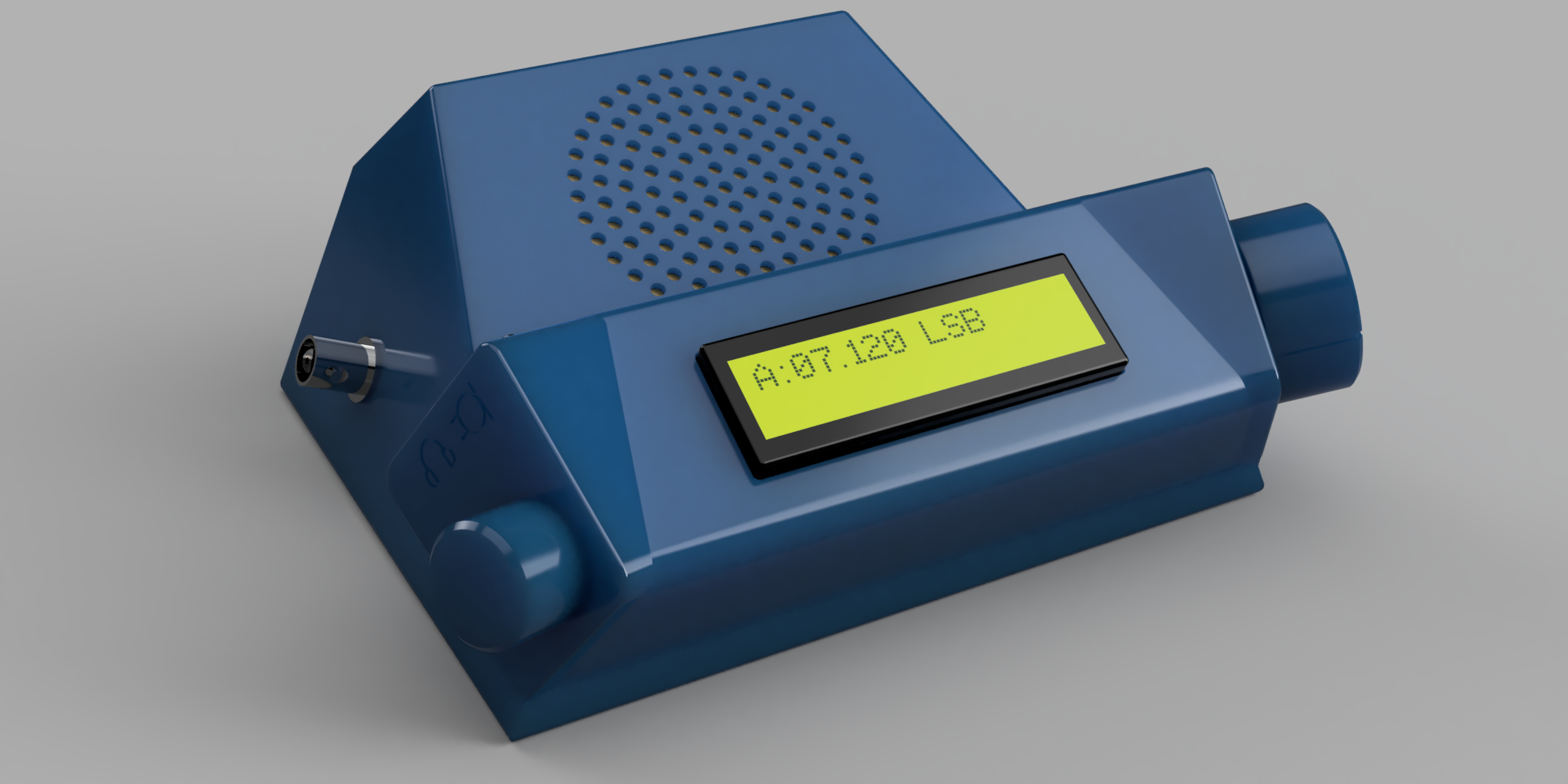
The DC40 is tuned using a digital encoder. I initially tried a cheap $3.00 encoder but wasn’t at all happy with the feel. Instead I ordered a Bourns EM14 optical encoder from Arrow that provides 64 pulses per revolution. By the way, my experience with Arrow has been very positive, despite the fact that the order wasn’t shipped until I contacted them two weeks after placing it, and then the shipping container for the encoder arrived slightly opened and empty. Support was excellent however and a replacement arrived two days later. Other stuff ordered from Arrow has been on time and in perfect shape.
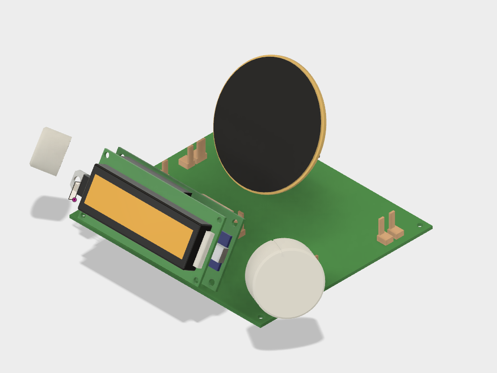
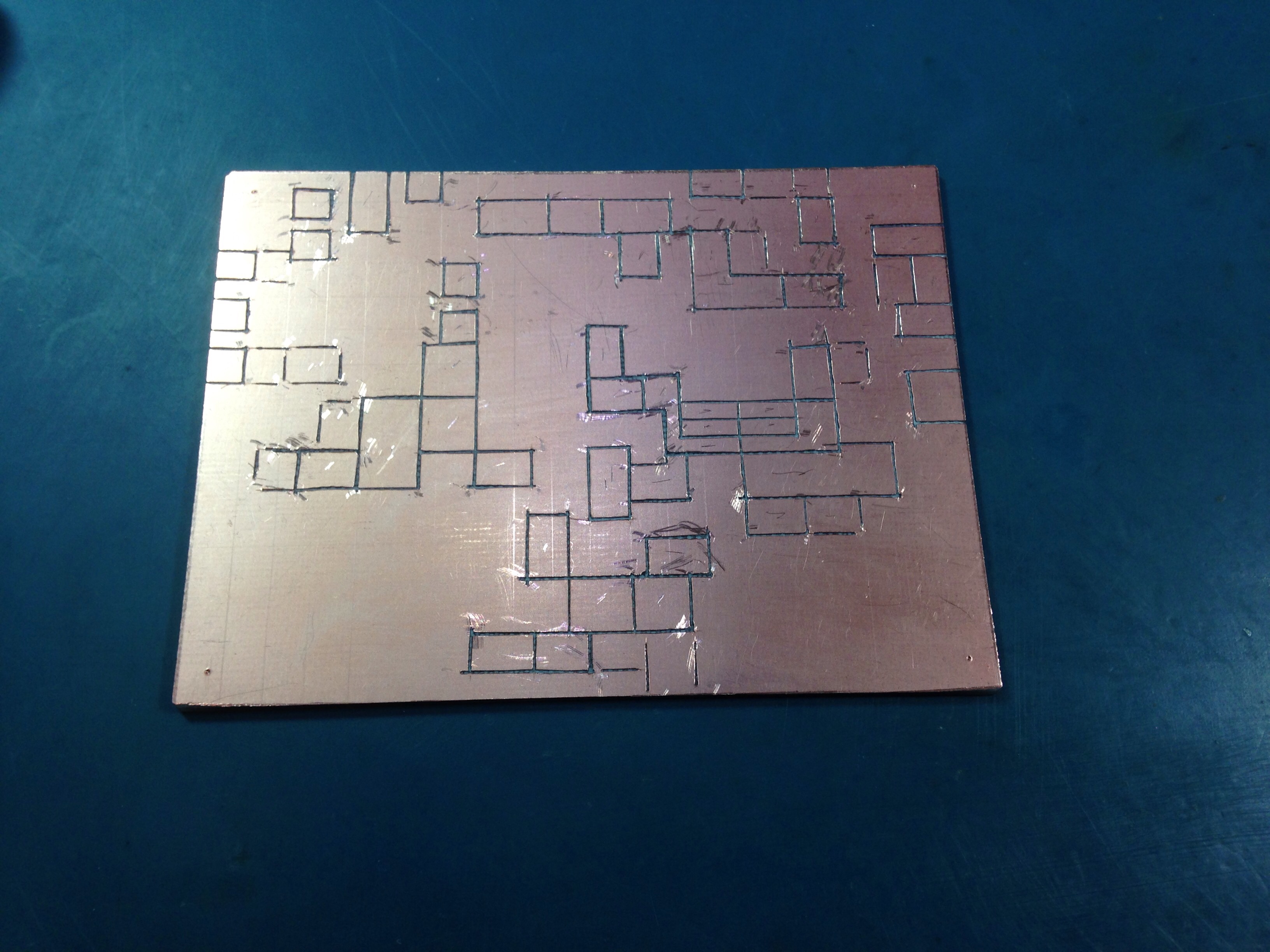
Construction

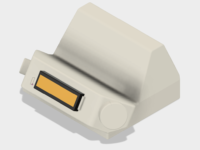
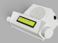
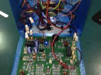
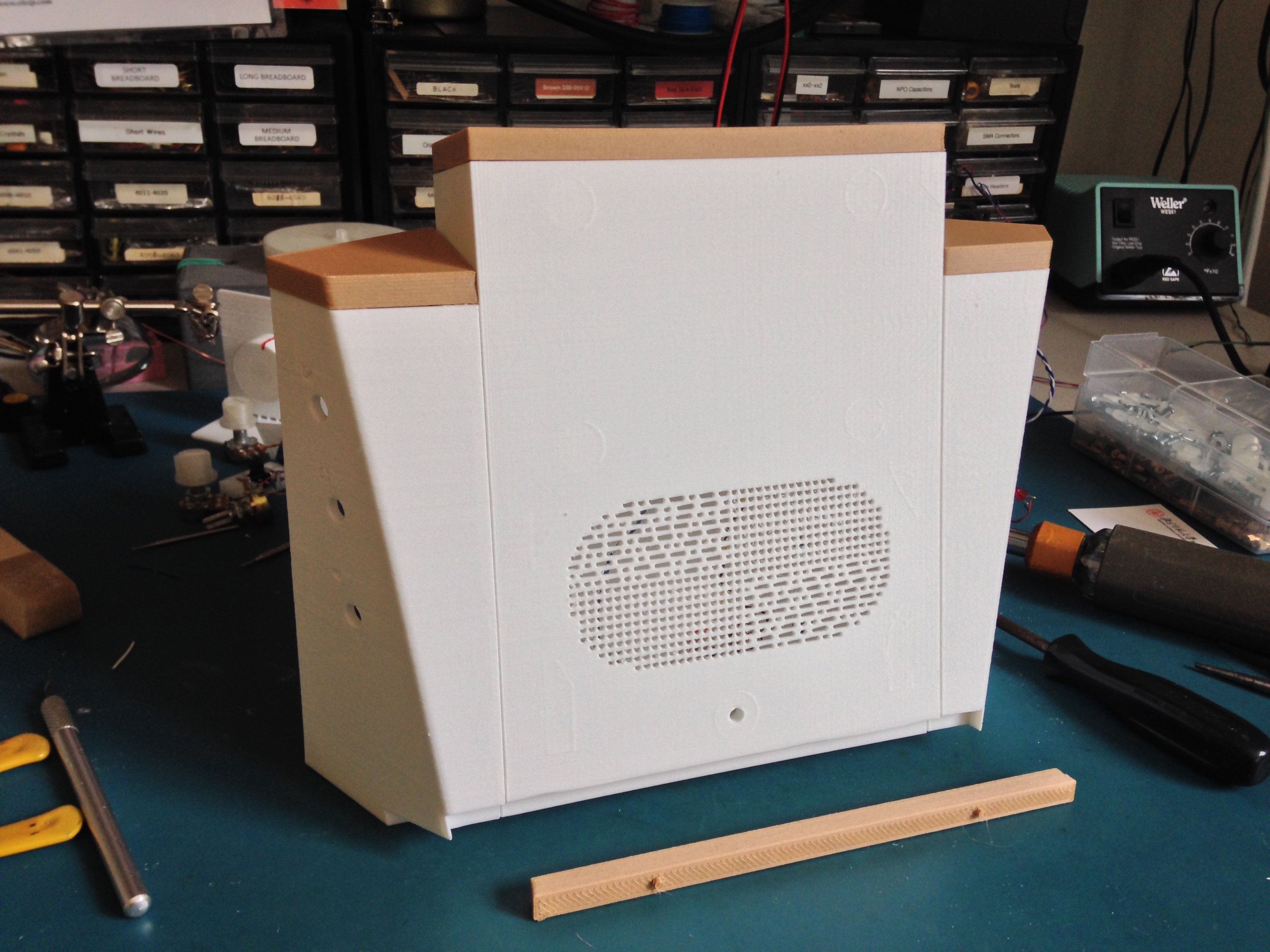
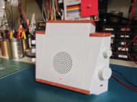
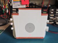
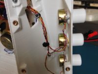
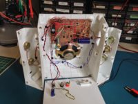
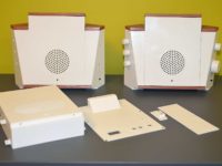
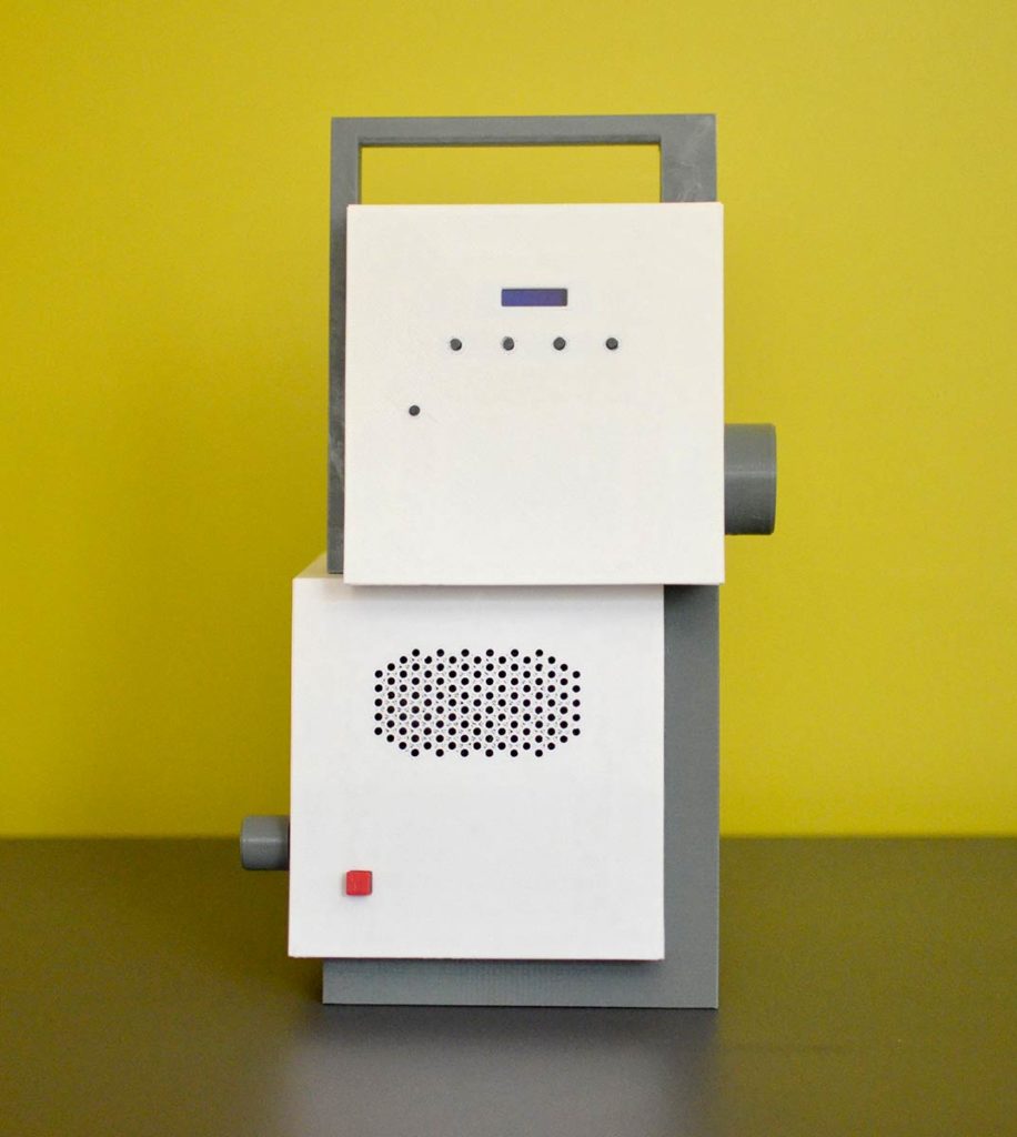
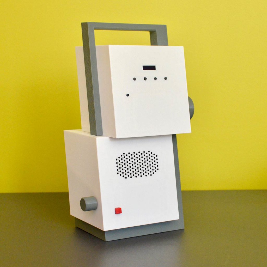
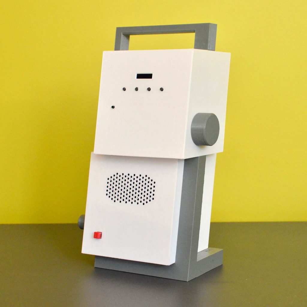
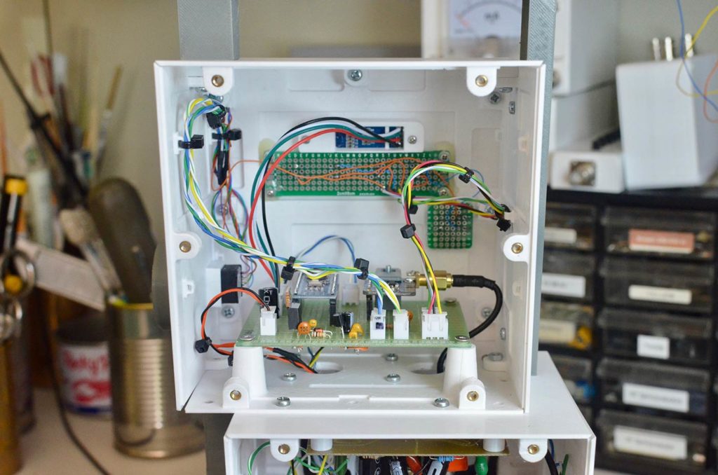
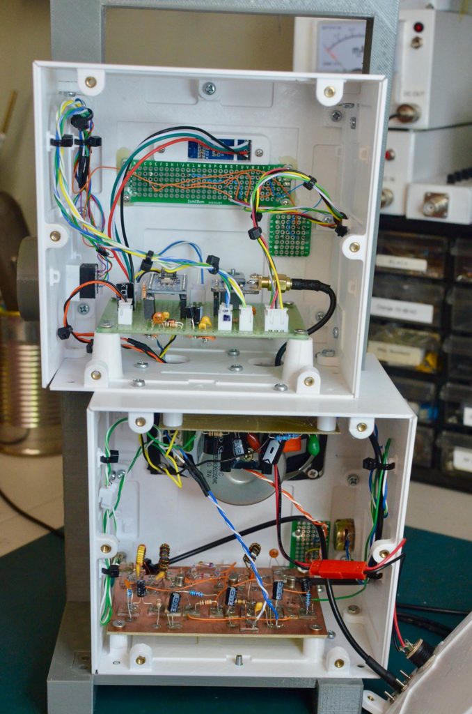
The radio is enclosed in two boxes, one for analog and the other for digital circuits; to avoid interference between the digital signals and the analog radio signals, the components are placed on separate boards. Digital circuits are on the top box and the radio/audio circuits are in the lower box.
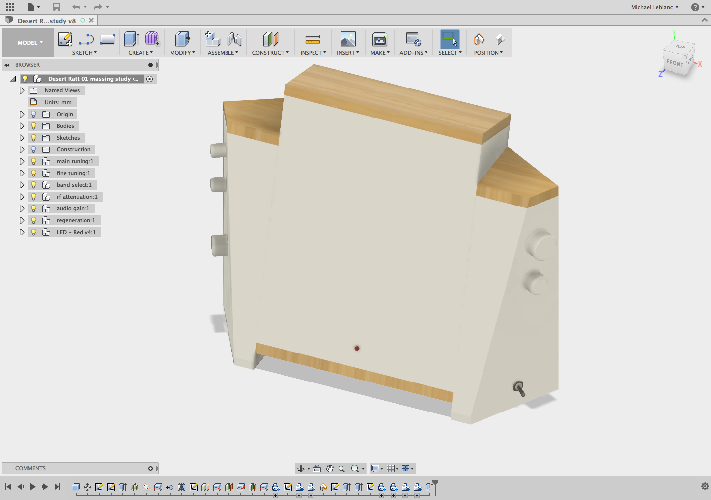
DC40 under construction
The radio ‘al fresco’, with the tuning section on the breadboard at the left, and the completed radio- and audio-frequency boards on the right.

Enclosure

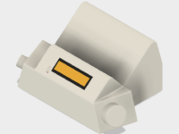
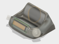
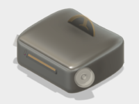
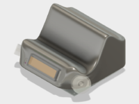
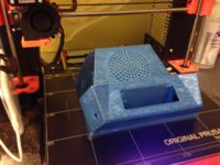
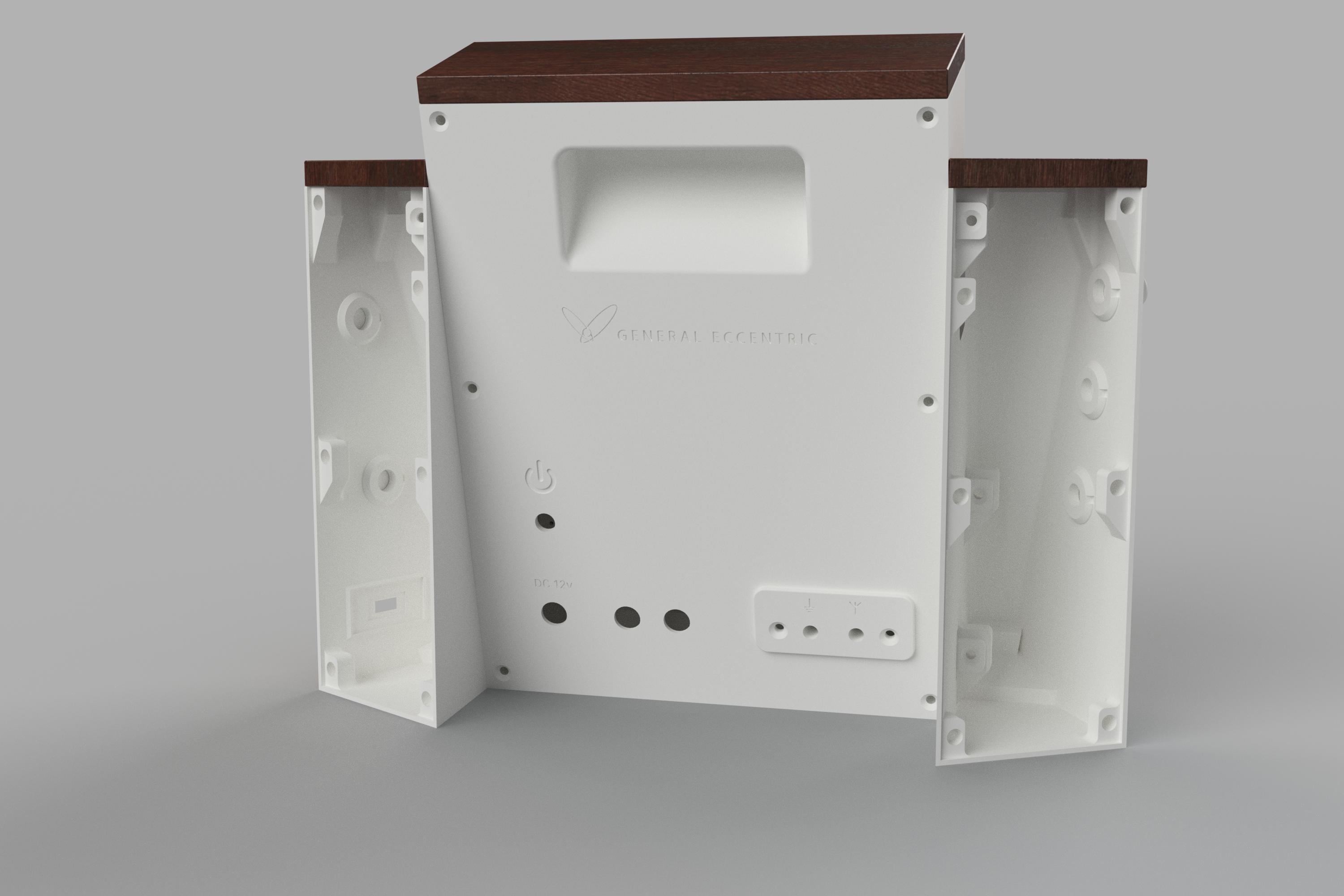
The enclosure was designed using Autodesk Fusion360 and 3D printed using PETG filament on my Prusa i3 Mk2.

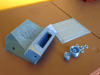
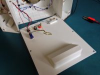
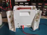
In contrast to my previous and previous 3D modeled enclosures, this one is designed so that each facet of each box is printed separately and later bolted together. Because each facet is printed face-down, the surface is very smooth and flat. The disadvantage to this approach is the “bolting-together” bit.

One might use the term ‘nightmare’ to describe it. Although Fusion360 makes it easy to ensure that parts mate well, it was up to me and my tiny brain to try to visualize how I would be able to bolt the pieces together. To my credit, for the most part my design ensures that I could torque each screw without other parts of the enclosure interfering—if I assembled things in the correct order. However, multiple times during assembly I had to disassemble parts because the arrangement obscured or interfered with other connections that had to be made.

DC40 under construction
Assembling the lower box.
DC40 under construction
The lower box assembled, with the digital board.

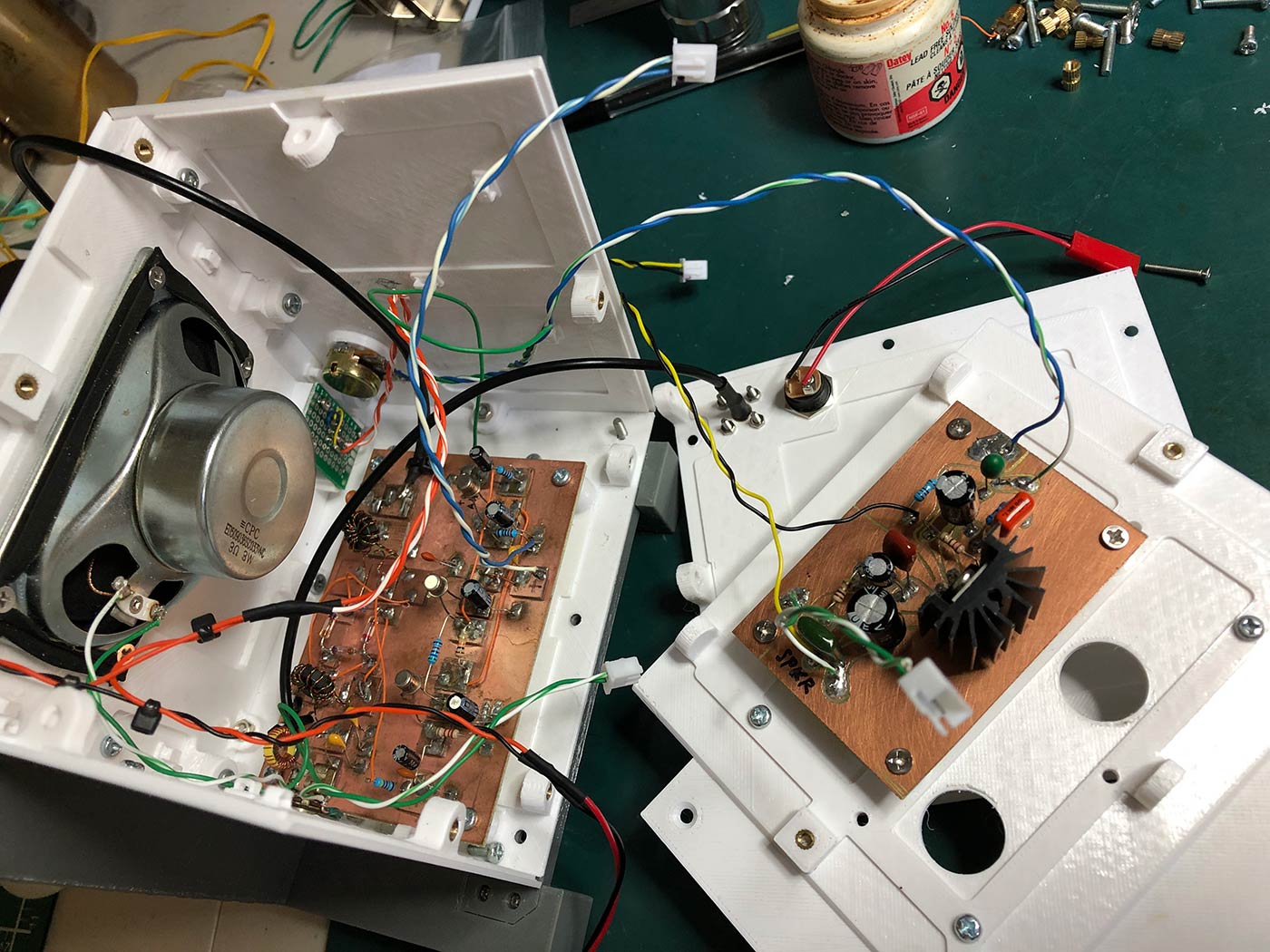
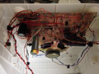
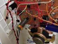
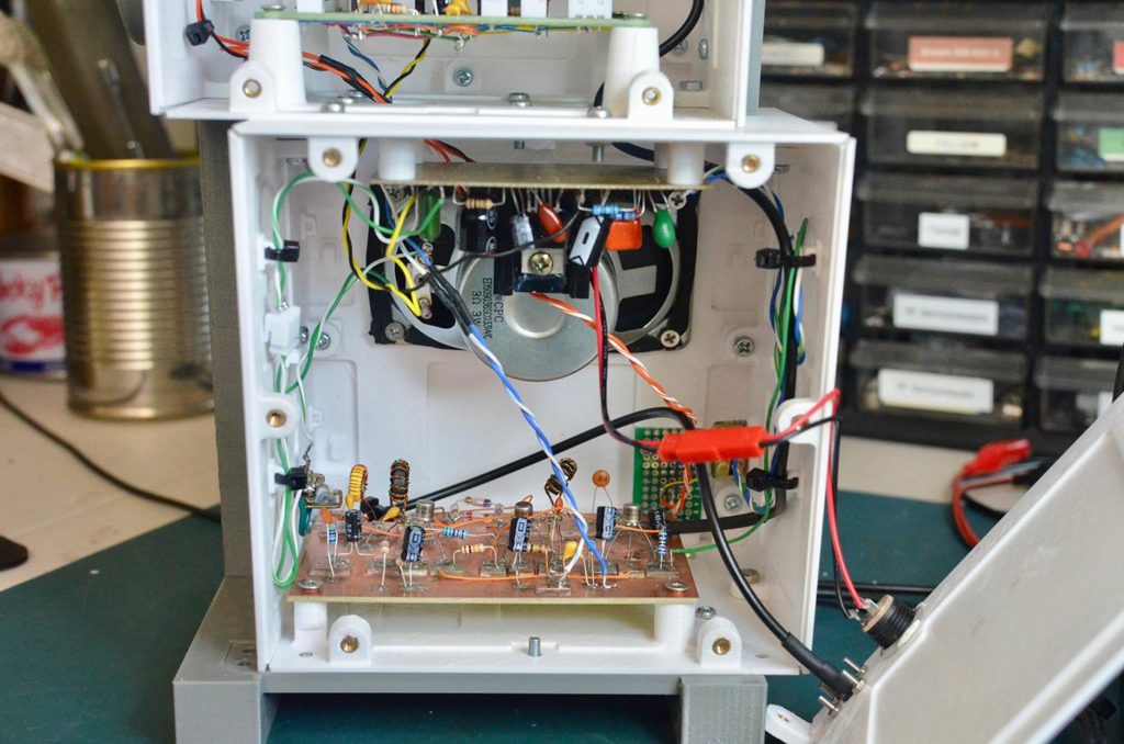
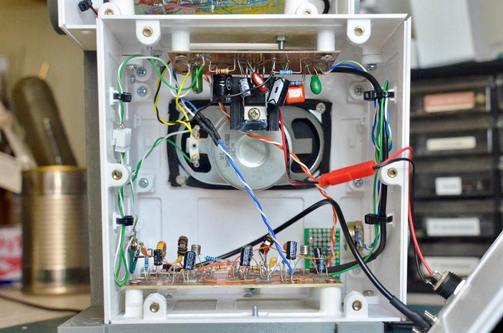
However, over the course of a few days, I was able to fitfully achieve complete assembly. I incorporated holds on the insides of some of the facets to facilitate using nylon ties to organize the inter-board wiring.

Here’s video of the radio in operation:

BITX40 Ergonomic Enclosure

Bitx40 design 10 v21

Back in April, as a birthday present to myself, I received a BITX40, an inexpensive 40-metre band SSB transceiver, designed by the brilliant radio amateur from India VU2ESE Ashhar Farhan.

Farhan is well-known among amateur radio homebrewers, and the BITX40 board has been purchased by thousands by enthusiasts around the world. It’s been designed specifically to facilitate experimentation, and you can find hacks and mods on the BITX20 discussion group, the Bitx Hacks site and on Github.

The BITX40 comes in a plastic dollar-store box: the bare board and some sockets, potentiometers, a tiny electret microphone, connectors and other hardware, and once the buyer solders these things on, adds 12v battery power– ‘bob’s yer uncle’– you have a working SSB rig. We call it al fresco operating.

But it’s really just a board, and it needs its own home. In keeping with the homebrew ethos of the BITX, users are designing cases and posting them. Bill Meara’s Soldersmoke blog/podcast regularly features BITX40 radios using powder-coated steel mesh, a metal popcorn box, a peppermint bark tin, and even a cakepan. Talk about retro, how homebrew can you get?

However, having a couple of months earlier bought a Prusa i3 Mk2, I thought that I’d like to design and build a 3D printed box for my new BITX.

The BITX40, being a very economical design, lacks many of the extras that grace more commercial rigs, like a signal-strength meter, CAT (remote) control by computer, or even AGC (automatic gain control). Without AGC, you can tune across the dial at weak stations and then all of a sudden be blown out of your chair by a strong station. AGC prevents that, by automatically adjusting the signal stronger or weaker, as required. Not too hot, not too cold. Just right.

So the absence of AGC requires the operator to use both hands: one for the volume control, and the other for tuning. In that sense, it’s a lot like a regenerative radio. And if you’ve read my previous post, I discovered that improper positioning of these controls can eventually get uncomfortable. Because we’re used to the conventional “dials-and-speaker-facing-front” radio case, it’s not something we’re aware of. But once you use a radio where the controls are ergonomically-placed, the experience becomes much more pleasurable.

My concept is different from other box designs because it’s ergonomically more efficient–the volume and tuning dials are positioned for ease of use and the speaker is tilted up towards the operator’s head. It’s small and has a much larger heat sink to accommodate 100% duty cycle transmissions that digital modes require. The design for the BITX40 evolved over several weeks; I started just playing around with Fusion 360 without making much headway. I experimented with the Sculpt environment in 360. I found it unwieldy and went back to Modelling. I made a total of 9 false starts before settling on a final design.


About halfway through this process, I realized that I was designing the shell without taking full account of what needed to go inside. So I modelled facsimiles of the BITX40 board and all the other components, so I created a “starting point” model from which all later models would derive:

BITX40 design start
BITX40 design start

Here’s a final render of the enclosure using a translucent blue, meant to represent a PET filament that I planned to use:

BITX40 Model Render
BITX40 Model Render

And here are some photos of the actual enclosure during printing, assembly and use:

The model is available for download on Thingiverse. I also designed a small microphone enclosure that you can also print out.

Desert Ratt 2 (Second Build)

I’m embarrassed that it’s taken me this long to get this post out. It’s currently nearing the end of August, and I started this project in mid-March. It was really wrapped up in late April, but I had to wait for parts to come from Asia for the enclosure, and they didn’t arrive until June, and then the summer arrived. Oh well.

I benefited from the experience of the first build: I got a good sense of how much space the individual components required, and how to best position the sub-assemblies relative to each other. I had also received my Prusa i3 Mk 2 3D printer with the intention of making boxes for these projects. My thinking evolved from making a presentable box for the radio to thinking about how I actually used the radio, and how to position the controls for most comfort and efficiency.


Here’s my design journal:

March 14, 2017:

PC Board
PC board before soldering

This build will use mainly surface mount components on a board which is half the size of the first one. It measures 100x75mm. The islands that I cut in the copper are sized for surface mount resistors and capacitors. Since most of my experimentation was on the first build, I had confidence to concentrate the components. Radios that have closer connections between components are also usually better performers.


March 15:

Assembled board
Parts are now soldered on.

Assembled board
Now ready for power up. And thankfully, no magic smoke has escaped!

A storm took down the antenna wire attached to the front of the house last night. The hemp string attaching it to the tree gave way. The wire (from a CAT5 cable) is very strong and has lasted two years without breaking. Environment Canada recorded wind gusts up to 109 km/h which is approaching minor hurricane speed. Main vertical antenna in the back yard is unaffected.

Most of the SMT components are now soldered down.

March 21: 

Completed most of the components and peripherals. After a couple of minor revisions, this radio now works — even better than the first! Although band conditions are very bad (minor storm and geomagnetic instability), I’m still able to receive a couple of stations over the noise and fading in and out. Fidelity seems much better on this radio.

Geomagnetic Conditions
Reception is Poor Poor Poor Poor Poor Poor Poor Poor


Enclosure

”It’s not just a box!“

If you’ve ever spent any time in front of a regenerative radio, it doesn’t take long to understand why, despite the excellent sound, dynamic range and overall performance of the design, most radios that work in the medium and high frequency broadcast and shortwave bands are not regens. They’re use different designs that allow the user to tune to a station and then leave it. One big disadvantage of regens is the fact that you have to constantly and carefully adjust the feedback and tuning to get the best reception. There’s a challenge to pulling out a distant signal using one of these radios, and you need two hands to do it.

radio-ergonomics-front
Position of hands on radio dials, from the front

radio-ergonomics-top
Position of hands, from top

That brings up an ergonomic issue: conventional radios are boxes with a speaker and control widgets facing outward from the front. This arrangement serves the average listener reasonably well; the radio is tuned once or twice in an hour and most of the time the listener is not touching the radio at all, so it really doesn’t matter where the controls are.

However, because regenerative radios require constant attention, I found that my hands and arms started getting a little uncomfortable after 15 minutes or so of constant adjustment of the dials. After a few days of using it and thinking about it, I realized that if the controls were on the front, an operator’s hand/wrist/arm had to be contorted into an unnatural and eventually uncomfortable position.

So my next question was “if the radio box resulted in discomfort, what would be more comfortable?” I surmised that if I were able to turn the rotary controls on an angle so that they don’t face directly at the user, but rather faced perpendicular to the user’s forearm, it would result in a more natural control position. I also thought that the front of the radio should be angled upwards slightly, since the radio will be on a desktop: on a ‘box’ radio that is positioned on a desk in front of a user, the speaker is aimed at the listener’s upper chest. The speaker should be pointed directly at the listener’s head, since that’s where her ears are!

Screen Shot of Design in Fusion 360

Here’s the design as it looked using Fusion 360 in the middle of my development cycle. The design consists of a main centre unit, which holds the circuit board and the speaker, and two side pieces which are bolted to the main cabinet and which hold the user interface items. The enclosure is meant to be entirely 3D printed. The wood too!


Adding a Relay for Band Changing

March 23:

Adding a band switch relay (closeup)

The radio is capable of tuning to two bands: from around 6.5-8MHz and from 9-12MHz. This is done by flipping a toggle switch. The switch itself is some distance from the circuit board, which means that the long wires to and from the switch are likely to adversely affect the circuit. After playing with it al fresco, I made one modification to reduce the length of wire to and from the circuit: I replaced the long leads (20cm) for the band switch with much shorter leads (4cm) to an HK23F-DC12V relay. The relay is actuated by the band switch on the far side of the radio, but the RF signals that are re-routed in the band switch are much shorter. This probably increases Q (makes for sharper tuning) and lowers the total capacitance of the band switch circuit to the values defined by the two small 10pF and 47pF caps.

Here’s my final working schematic:

Desert Ratt 2 Final drawing
Desert Ratt 2 Final Drawing


Designing the Cabinet for Production

By mid-April, I had printed a draft enclosure to see if it everything would fit together.

No 90° overhangs
No 90° overhangs that are unprintable

Printing in 3D has its own opportunities and limitations. Because it prints up from the bed layer by layer, certain structures such as overhangs longer than about 1cm are not possible without first defining support structures that can be removed after the print is completed. However, careful design can reduce and sometimes even eliminate support material structures. The Prusa i3 Mk2 is capable of printing 45° overhangs. In the case of this enclosure, very few supports were used; if there were overhangs, such as the surfaces that hold the threaded brass inserts, these were extended to between 30 and 40°, as you can see in the detail of this rendering.

Desert Ratt 2, Draft Enclosure April 16:
  • Centre: need some strengthening fixed
  • Circuit board: use 2.0 mm holes, 4mm deep, add 1.5mm washers fixed
  • Band Switch: placement guides not large enough: block is 15 x 31 mm fixed
  • [Small, medium knobs need at least 5.9 mm dia -they appear to be 5.8mm – is this due to draft mode printing?]
  • Knobs need to have longer skirts – try 4mm fixed
  • add dial dots on main tuning fixed
  • add diode in front of VCC not done.
  • add headphone jack on back? not done.
  • swap out pots for new ones fixed
  • Speaker magnet collides with centre back – replaced

This last point was a surprise; although I thought I had measured everything, even to the point of modelling-in the components, I didn’t model the speaker correctly and the test fit quickly showed that the back panel wouldn’t fit with this large speaker. So it just goes to show: you can have fantastic design software but there’s just no replacement for printing one out and doing a test fit.

Edit: Actually, I printed two full copies in the 0.20 mm “normal” detail setting before printing the final using the 0.15mm “optimal” detail.

Here’s a Fusion 360 render of the back:

Back view render
Back view render


And here are a couple of photos of the actual test fit:
Desert Ratt 2, Draft Enclosure April 18
  • Centre re-designed with web strengtheners
  • replaced old grille with Dieter Rams 1973 grille: “steal from the best”
  • added Dial Dots around the Main Tune pot on the right UI
  • vertical web strengtheners will not print in Draft mode, printed in normal mode
  • fashioned clips and mounted new circular speaker
  • swapped out old potentiometers
  • stained wood pieces
  • added “UI clips” on the cable holes to bring the shells closer together
  • listened in the evening many strong stations… great sound! It’s amazing how much better a speaker can sound when you put it in a box.
Desert Ratt 2, Draft Enclosure April 19
  • tried listening in morning: unable to tune. Much back and forth. Problem seemed to be located in Regen circuitry & pot. Replaced transistor closest to Regen pot. Finally, replaced the Regen pot. Pot went bad!
  • bundled cables with nylon ties
  • urethaned wood

The 3D printed wood pieces were printed from Spool3D “light brown wood” PLA filament. Spool3D is a Canadian company and I buy all my filament from them. My only complaint is that I’ve never been able to get a proper answer from them on what Munsell values they use for their coloured filaments.

Test Fit (front)

Test Fit (back)
Test Fit (back)

The wood colour is, as the name suggests, “light brown”, and I was able to stain it (after sanding) with three coats and then lightly give it one coat of urethane. The rest of the cabinet used Spool3D White PLA.

The three sections are screwed together using M3 screws into brass inserts. The inserts are placed on the end of a hot soldering iron, and after about 5 seconds you can press them into place in the plastic and once they cool, they are bonded into the plastic. I found this technique on Youtube.

One last change was the speaker and speaker grille. My initial idea for the grille was to make holes that mimic the dot-dash of morse code. When I transitioned to a smaller round speaker, I stole Dieter Ram’s TP1 record player grille design. In the end I made one final further refinement by making the grille slightly convex.

The final enclosure was printed in “natural” PLA. This was a mistake, because natural PLA is slightly translucent, and I liked the white material better. I resorted to sanding, priming and spray painting the final print—a lot of work that could have been avoided had I printed in white. While PLA is great to print with, it’s difficult to sand and otherwise work with. And because PLA has a melting point of 60° C, I can’t place it in hot environments like a closed-up car in the summer time.

One last observation: it’s amazing how much better a radio sounds when you place the speaker in an enclosure. Or a box.

Here’s a short video of the radio. Unfortunately it was done on an evening with a K index of 4 (unstable geomagnetic conditions). More photos below the video.