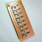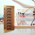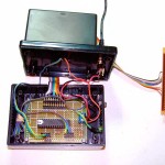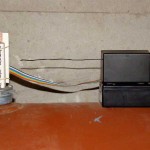

In “Fun with Reed Switches” I mentioned that field testing of the Fuel Gauge system (as originally designed) was unsuccessful. I attributed the failure to the sensor array, which uses latching hall effect switches. I suspect that the hall effect does not work with extremely slow movements, such as that of the mechanical gauge on the oil tank.

So I set out to replace the hall effect array with reed switches. The switches are surface-mounted on protoboard as described here.
I also took the opportunity to completely rework the sender unit, including replacing the Arduino Mini Pro with a minimal ATMEGA8 chip using its internal oscillator. I’ll save my Mini Pro for another project that either requires the 16 MHz clock speed or its 16kb of program memory.

In the original design, the entire unit enclosed the mechanical gauge. In the new design, the sensor array and the microcontroller/transmitter are separate, connected by a ribbon cable.
The Arduino sketch is also optimized (see below). Instead of nested if/else conditionals, I’ve used a much more elegant method. For each sensor level, the system looks for a closed reed switch. When it finds one, it uses bitwise ANDing to match the number of the closed reed switch to a binary value. This binary value is then presented to the transmitter.
/* Oil tank level using reed switches
 v. 2.01 Mar. 21 2010
 by Michael B. LeBlanc, NSCAD University  */

int level;   //the reading from the oil tank gauge

void setup() {
 pinMode(10, OUTPUT);  // warning LED
 pinMode(11, OUTPUT);  // D0 to TX
 pinMode(12, OUTPUT);  // D1 to TX
 pinMode(13, OUTPUT);  // D2 to TX
 Serial.begin(9600);   //FOR TESTING
}

int sensorpin=0;       // What sensor pin we are checking
byte binary;           // This will hold the binary value of the sensor pin
byte D0;               // This will hold the one's bit
byte D1;               // This will hold the two's bit
byte D2;               // This will hold the four's bit

void loop() {
 for (int i=0; i<8; i++)                // Start with sensor 0 and work up to sensor 7
 {
 sensorpin = i + 2;                   // Add 2 to calculate which Arduino sensor pin we want to check
 if (digitalRead(sensorpin) == HIGH)  // If the switch is closed:
 {

 D0 = B001 & i;                     // bitwise AND the binary value of the sensor to mask the 1's bit

 digitalWrite(11,D0);               // write the value to Arduino pin 11

 D1 = B010 & i;                     // bitwise AND the binary value of the sensor to mask the 2's bit
 D1 = D1 >> 1;

 digitalWrite(12,D1);               // write the value to Arduino pin 12

 D2 = B100 & i;                     // bitwise AND the binary value of the sensor to mask the 4's bit
 D2 = D2 >> 2;

 digitalWrite(13,D2);               // write the value to Arduino pin 12
 }
 }

 delay(100);

 // blink LEDs on pin 10 if tank is empty
 if ((digitalRead(10)==LOW) && (digitalRead(2) == HIGH))
 {
 digitalWrite(10,HIGH);
 delay(100);
 }
 else
 {
 digitalWrite(10,LOW);
 }
}
![]()
Remote Fuel Oil Tank Gauge by Michael B LeBlanc is licensed under a Creative Commons Attribution-Noncommercial-Share Alike 2.5 Canada License.
Contact the writer for permissions beyond the scope of this license.