Here’s the elevator pitch:
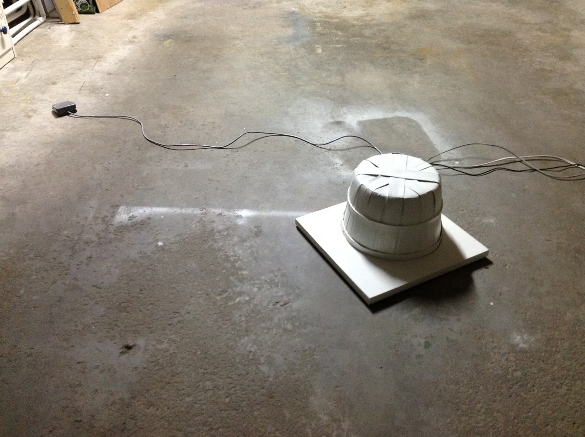
An electric lamp doesn’t like anyone to see it when it’s turned on. It hides under a bushel basket and when it’s exposed, it fades out. When the basket is replaced, it lights back up.
This is another project in the series “The Technology of Good Intentions”: these works are intended to focus the viewer on the role of failure in design.

The entire assemblage uses two X-10 modules: an PL513 Power Line Interface (PDF) and an LM465-equivalent lamp module. The PL513 provides an interface from the microcontroller to the X-10 protocol, and the LM465 accepts commands (such as dim light and brighten light) to control the light.
Why X-10?
A primary project requirement was the ability to have the microcontroller dim and brighten the lamp on command. I investigated three ways of doing this:
- Making a light dimmer using a triac and opto-isolation. This is easier said than done. I found that there are complications, such as buzzing, radio-frequency interference, and of course, safety, since I was playing with 120v AC current. I experimented with triac control using low-voltage AC, and decided it wasn’t worth the effort in trying to overcome the drawbacks just to save a few dollars.
- Buying a hardware-store light dimmer switch and using an actuator—such as a servo or stepper motor—to engage the dimming and brightening. At an early stage of the design process, I had decided that the project was much more complicated than I first thought, and I wanted to avoid making it look like a Rube Goldberg device.
- Using the X-10 system, which transmits commands through household AC power. The Power Line Interface module uses 4 wires to connect to a 5-volt microcontroller, via a standard RJ11 telephone plug.
I had used the X-10 as an automatic light dimmer years ago, and though I found it sometimes quirky, it worked 95% of the time and was super-safe. Plus, no moving parts were involved. I chose door number three.
How’s It Work?

- The overturned basket is closed. The user activates the gadget using a foot-switch.
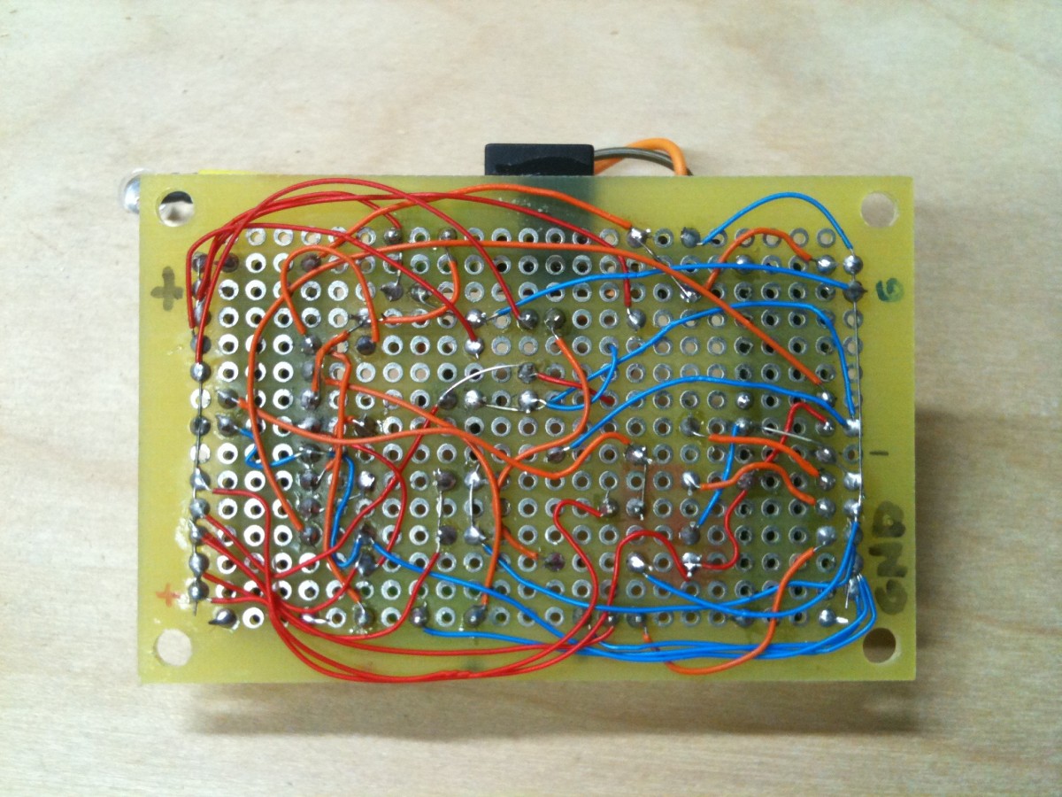
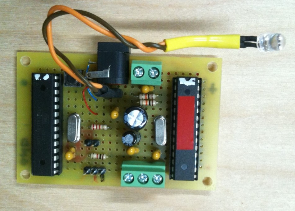
- The switch sends an electrical pulse to a box enclosing two interlinked ATMEGA168 microcontrollers. In this case, the “Master” controller receives the foot-switch signal.
- The Master ATMEGA signals the “Slave” controller to direct a servo motor to open the basket. The sole purpose of the Slave controller is to generate the pulse-width modulation commands to the servo motor.
- The Master controller also sends a “dim lamp” message to the X-10 power line interface, which is plugged into a 120-volt power wall socket. The interface translates the 5-volt pulse generated by the Master controller into an encoded series of pulses on a 120 kHz carrier wave, on top of the 60 Hz AC power signal.
- The commands generated by the X-10 power line interface are received by the X-10 lamp module.
- The lamp under the basket dims as the basket opens.
Why TWO Microcontrollers?

The Master Control microcontroller handles the foot-switch input, orchestrates the timing of the opening/closing of the basket (using commands to the Slave Control unit) and the lamp dimming. Initially, I had no idea that the project would require two; there are enough analog and digital pins on one microcontroller to do it all, but—and I’m not absolutely certain about this because I didn’t keep detailed notes about this—I think that I was forced into a dual processor arrangement because of the complexity of the program timing. As I designed the circuit, I came to the realization that the timing required by the various elements was going to be difficult for me to accomplish as an amateur C-coder if I tried to stuff it all into one controller. So I don’t want to say that “it can’t be done with one chip”. I just decided that it was simpler for me to compartmentalize the various tasks with hardware. So I added another ATMEGA168, at an added cost of about $5.00.
Physical Considerations
The Lamp

Before starting the design, I had ordered an LED light bulb from Dealextreme: this 128-LED bulb uses an E27 socket (the familiar screw-in type found in most incandescent and compact fluorescent bulbs) and draws 6 watts. It has a diffusion enclosure that makes it look somewhat like a typical light bulb. This LED bulb was preferable because I wanted the light to stay on under the basket when it was closed. It’s lower current draw resulted in less heating in a small enclosed space. There was only one problem: when combined with the X-10 dimmer, I discovered that this bulb wasn’t fully ‘dimmable’!
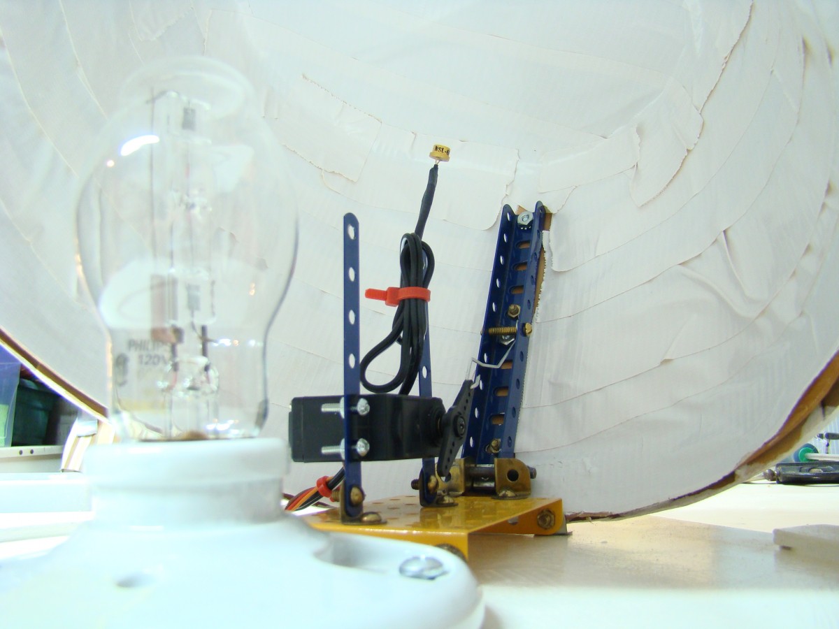
After I recovered from this mild disappointment, I elected to use a clear “BT” shaped halogen lamp. Halogens put out a lot of heat, so I had to add a routine to dim the lamp after a short delay whenever the basket covered the lamp. Additionally, although this dimming routine never failed while it was on the testbed, I was concerned that this X-10 ‘dim’ command might, at times, fail to dim the lamp, heating the inside of the basket, causing a fire hazard. So I added a second level of safety: a CDS cell monitors the light level when the basket is fully closed. After the basket closes and the unit goes into idle, the state of the light sensor is polled: if the light level is above a certain level, the X-10 issues an immediate “light off” command. This certainly doesn’t cover all contingencies—especially if the X-10 suddenly fails while the lamp is on—but I’m less concerned about the fire hazard issue now.
Construction Notes
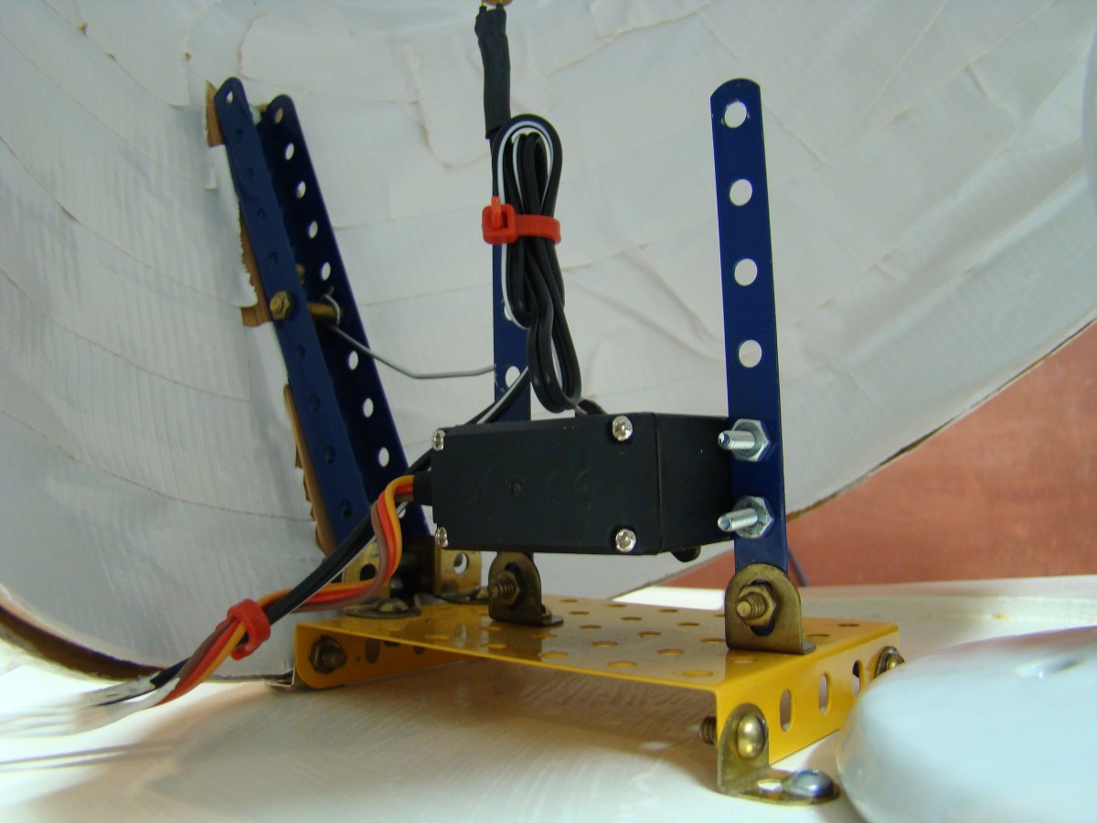
 The servo and linkages are bolted together using Meccano hardware. The main hinge that connects the base of the basket with the base is also Meccano: to secure the hinge, I used a dab of thread locker on the bolts. The servo is a heavy-duty unit (SG-5010) that has metal gears and a stall torque of 3kg. As I found in design and testing, this amount of torque is enough to wrap the 17 gauge steel linkage wire around the servo shaft!
The Next Iteration…
The next version, if there is one, will dispense with the X-10 control and use high-powered DC LED illumination. Rather than a light in the centre of the base, I would consider attaching the lighting to the inside of the basket.
View the Shy Light Schematic (PDF), and here’s the Arduino code for the Master and Slave microcontrollers (Github).
Shy Light Mechanical Drawing (PDF)
Shy Light by Michael B LeBlanc is licensed under a Creative Commons Attribution-Noncommercial-Share Alike 2.5 Canada License.
Contact the writer for permissions beyond the scope of this license.