Tag Archives: Holtek

Clock with Tics (using SURE 0832)

Clock with Tics using Sure Electronics 0832

When I posted the original prototype of the Clock with Tics, Arduino Forum member mowcius commented that all the wiring and matrix driving could be greatly simplified with the LED matrices from Sure Electronics. While I was aware of the Nanjing-based company, I had not bought anything from them, nor had I seen them in the several electronics supermarkets that I had stumbled upon when I last visited the city.

Long story short: I bought a yellow LED 0832 module on ebay from Sure: they are remarkably cheap, about $9 each. Four of them can be strung together to make a respectable scrolling-message sign. Single units can be easily driven by an Arduino Duemilanove, but you can also buy a driver board that handles the higher current requirements if you need to string several together.

When I received it, I was busy with other matters and I put it aside. When I had a few hours here and there, I pulled it out and tried making the connection with an Arduino. I was not successful in getting past the self-test mode.

Last weekend, while waiting for replacement parts to arrive (also from Sure Electronics, by the way) for my ‘Shy Dildo’ project, I thought I’d attack the problem one last time. I had earlier unsuccessfully scoured the net for references to the 0832 module, but this time, I looked for “HT-1632”, which is the Holtek driver chip that’s used in the Sure module. Bingo!

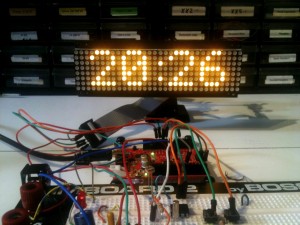
I found several Arduino libraries that purport to work with HT1632 units. The first one that I successfully connected was from MakeHackVoid; it demonstrated the pin connections between the 0832 and the Arduino, and linked to libraries that enabled the 0832 to do the ‘crawling words’ scrolling thing. I spent most of the weekend playing with the code and re-working the somewhat erratic-looking font that came supplied with it. I could not, however, simply write a static string to the 0832.

Then I found Miles Burton’s library. This library has good documentation, and made it possible for me, a dopey artist, to figure out how to adapt the ‘Clock with Tics’ code from the presentation prototype to the Sure 0832 matrix. The process of getting to this point was complicated by several factors:

  1. A bad connection in a breadboard hookup wire
  2. Difficulties in sorting out the five different libraries that I had experimented with during the course of three days.
  3. A poor understanding (on my part) of the nature of chars and strings. I was unable to get my head around these concepts, and why the C language makes translation between chars and strings (and among other formats) so complicated. The Arduino String Library has limited documentation, and there doesn’t seem to be much in the way of helpful information elsewhere online. I don’t have any formal training in computer programming, and until Arduino I had avoided C.

The circuit for the new model should fit comfortably on one 6x9cm circuit board. I estimate that it is about 90% simpler to assemble. It has an added feature of a CDS (light cell) that allows the display to fade or brighten depending on the ambient light.

Clock with Tics for SURE Source Code (Github)

Clock with Tics for SURE Schematic (PDF)

A Design for a Remote Fuel Oil Gauge II

In my first post for this project I outlined its overall design. In this post I’ll describe the “sender” unit that senses the fuel oil level, interprets it as a three-bit number and sends this number to the receiver in the kitchen.

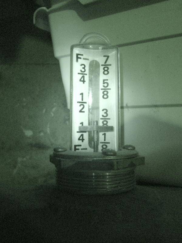
This is a photograph of the mechanical gauge, which shows the level as eights of a tank. The float that moves up or down will provide the shelf upon which I’ll glue a small rare earth magnet.

To ensure that the magnet is sensed, I had to do some careful measurements and calculations: the clear plastic covering of the gauge has a cross-section that is oval, and it is also tapered slightly so that it has a smaller diameter near the top.

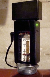
My plan was to fit a plastic box over the gauge so that the sensors would be as close as possible to the magnet, and to allow for visual inspection of the gauge at any time.

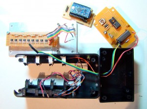
I mocked up a test using some scrap foamcore and blue modeling foam to see how a box could be snugly fitted to the gauge. I decided that a good solution would be to create carefully cut foamcore ribs for the inside of the box that would hold on to the sides of the gauge yet still allow for room of the sensor unit and other electronics. As I discovered later, I did not have enough room for the radio circuit, so I had to add another small box on top of the main box. If I do this again, I’ll use a bigger box.

I cut a long hole along the length of the box so that anyone could see the mechanical gauge, given enough light. The sender unit slides down over the gauge and can be easily removed for maintenance.

The SS461A hall effect sensors that I purchased from Jameco are “latching,” which means that when a magnet passes one in one direction, it turns on and stays on until the magnet passes in the opposite direction. This is good in one way, and bad in another.

The positive aspect of latching in this context means that, as the fuel oil tank is filled, the gauge goes up and progressively latches each sensor “on” as it passes. You could read the sensor array and it present it as a bargraph. As the oil is used and the level begins to move down, the topmost sensor is turned off, then the next in line is turned off, and so on.

The negative aspects of this arrangement only presents itself outside of normal operation. Say, for example, there is a power failure? How does the sensor array know where the magnet is? Furthermore, there is a “NOTICE” on the spec sheet that reads: “Interruption of power to a latching device may cause the output to change state when power is restored. If a magnetic field of sufficient strength is present, the sensor output will be in the condition dictated by the magnetic field.” In other words, you may get errors when the power is returned. Some sensors that were “off” before power was removed, could change to “on” and vice versa. I didn’t realize this until late in my testing. I need to keep an eye on it to see if this presents a problem in actual use.

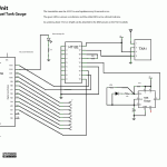
Sensor Main Logic Schematic
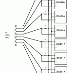
Sensor Array Schematic

The Sensor Main Logic Schematic shows that all the digital input/output pins on the Arduino are in use. D12 is used as a “low oil warning light”: when the level reaches the last sensor, this LED starts blinking on the sender unit. Most of the other digital pins are configured to accept input from eight hall effect sensors (refer to the Sensor Array Schematic).

The Holtek HT12E chip is an “encoder” that accepts a parallel 4-bit binary value (only 3 are used in this application) and sends it serially to an On-Shine TXA1 transmitter. The TXA1 is one half of a receiver circuit pair RXA27. These are normally used in radio-controlled toys, where simple commands like forward/reverse/right/left need to be communicated, or in simple security systems. The Holtek has an internal oscillator, configurable with a resistor between pins 15 and 16 (I’m using something close to 400k).

The Transmit Enable on pin 14 has to be low to send the data to the transmitter. In my original design, I wanted to transmit every 20 seconds, so I added a 555 timer chip in astable mode. This worked fine in test mode but before I closed up the boxes, I took the chip out and connected pin 14 to ground to force the unit to transmit all the time.

Arduino Sketch for the Sender Unit

The sketch tells the Arduino to poll each sensor from 7 to 0 (from the top sensor to the bottom sensor). If the sensor is “on”, then send the binary number of that sensor out to the transmitter. Once it hits a sensor that is “on” then it dumps out of the if/else loop.

/* version C of oil tank level
revised Sept. 23 09 to account for correct reading on
power-up
revised Oct. 5 09 to release pin 2 for use by radio transmitter
revised Feb. 16 2010 to refine sensor logic
revised Feb. 23 2010 to change active sensors (ignore sensor 10 rather than sensor 3)
by Michael B. LeBlanc, NSCAD University */

int level; //the reading from the oil tank gauge

void setup() {
pinMode(12, OUTPUT); // warning LED
pinMode(2, OUTPUT); // D0 to TX
pinMode(11, OUTPUT); // D1 to TX
pinMode(13, OUTPUT); // D2 to TX
}

void loop() {
// determine the gauge level
// start with the highest sensor and work down

int sensorValue = digitalRead(3);
if (sensorValue == 1)
{
level = 7;
digitalWrite(2,1);
digitalWrite(11,1);
digitalWrite(13,1);
}
else
{
int sensorValue = digitalRead(4);
if (sensorValue == 1)
{
level = 6;
digitalWrite(2,0);
digitalWrite(11,1);
digitalWrite(13,1);
}
else
{
int sensorValue = digitalRead(5);
if (sensorValue == 1)
{
level = 5;
digitalWrite(2,1);
digitalWrite(11,0);
digitalWrite(13,1);
}
else
{
int sensorValue = digitalRead(6);
if (sensorValue == 1)
{
level = 4;
digitalWrite(2,0);
digitalWrite(11,0);
digitalWrite(13,1);
}
else
{
int sensorValue = digitalRead(7);
if (sensorValue == 1)
{
level = 3;
digitalWrite(2,1);
digitalWrite(11,1);
digitalWrite(13,0);
}
else
{
int sensorValue = digitalRead(8);
if (sensorValue == 1)
{
level = 2;
digitalWrite(2,0);
digitalWrite(11,1);
digitalWrite(13,0);
}
else
{
int sensorValue = digitalRead(9);
if (sensorValue == 1)
{
level = 1;
digitalWrite(2,1);
digitalWrite(11,0);
digitalWrite(13,0);
}
else
{
level = 0;
digitalWrite(2,0);
digitalWrite(11,0);
digitalWrite(13,0);
}
}
}
}
}
}
}

delay(200);

// blink LEDs on pin 12 if tank is 1/8 full
if ((digitalRead(12)==LOW) && (level < 1))
{
digitalWrite(12,HIGH);
delay(100);
}
else
{
digitalWrite(12,LOW);
}
}


Creative Commons License
Remote Fuel Oil Tank Gauge by Michael B LeBlanc is licensed under a Creative Commons Attribution-Noncommercial-Share Alike 2.5 Canada License.
Permissions beyond the scope of this license may be available at mleblanc@nscad.ca.