All posts by Michael LeBlanc

Parallel Programming: Plumbing on Arduino

In real life, all sorts of things happen at the same time: the milk truck eases into your space, and somebody screams somewhere… But in programming, how do you chew gum and walk at the same time?

Today’s microprocessors—including the ATMEGA processors that power the Arduino—run by executing a linear stream of commands very, very quickly. The illusion of concurrency can be created and maintained if the processor is fast enough to make one action seem as though it is done at the same time, even if they are only one microsecond apart. Even so, there is a problem with the C/C++ language that the Arduino development environment uses when you want to manage concurrency.

Take this example: you want to blink a red LED on and off every 500 ms, and at the same time you want to blink a green LED on and off every 250 ms. The delay() function cannot be used, because delays basically put the processor into zombie mode, disabling it from receiving or sending any information. There are Arduino libraries available that can help the programmer with timing to juggle multiple actions, such as Metro, but they are wordy solutions, hamstrung by the linear nature of C itself.

Enter Plumbing, an Arduino interactive development environment which specializes in its ability to conceptualize and implement parallel programming. Plumbing is adapted from the language called occam-π (occam-pi). Occam-π, together with the Transterpreter (which allows Occam-π to be run on small microcontrollers like the AVR ATMEGA chips), runs on an open-sourced Java-based development toolchain.

Throughout the setup process, I referred to an excellent introductory book called Plumbing for the Arduino, by Matthew Jadud, Christian Jacobsen and Adam Sampson, freely available as a downloadable PDF file.

A short demonstration program

Setting up an Arduino Duemilanove for Plumbing is relatively straightforward. You need to install the latest JAVA distribution, which is available for all major operating systems. The Plumbing IDE is available for Mac, Windows or Ubuntu Linux, but since the dual-boot netbook I use for my development machine uses Ubuntu 10.10 (Maverick Meerkat), and Plumbing hasn’t caught up, I felt compelled to switch over to Windows XP.

Programming using Plumbing/occam-π on the Arduino is made possible when you upload the Transterpreter firmware into the Arduino. Nothing permanent is done to your Arduino unit in the process, because the firmware is really, in the words of the authors of Plumbing for the Arduino, just an overgrown Arduino sketch. So if you want to go back to Wiring, the conventional Arduino development environment, there’s nothing you need to do. The obvious drawback is that the Transterpreter takes up a good 23k of memory, leaving room for only small programs.

Once installed, the book guides you through parallel programming using Plumbing. One unusual thing (from my perspective as an artist/designer) is how the authors encourage the use of process diagrams to visualize what you’d like to do.

In this 11-line program, four LEDs blink at different rates, while a button toggles a fifth LED.

Clock with Tics (presentation prototype)

Clock with Tics is an Arduino-powered 24-hour digital clock that displays expletives at random intervals.

A clock ‘ticks’. A ‘tic’ (note the different spelling) can be a mental disorder and can manifest itself in a number of ways; most seriously, someone suffering from “Tourette’s Syndrome” will blurt out swearwords involuntarily. I had thought of titling this piece “Time for Tourettes”, but the clock itself is tasteless enough.

This artifact is part of my series “The Technology of Good Intentions” which focuses on ‘failure’ in design. In this case, who has not had an electrical widget that has ‘gone on the fritz’ and suffers from momentary lapses?

The Arduino code for this project is available under a Creative Commons Attribution-Noncommerical-Share Alike 2.5 Canada License. Most of the electronic parts were obtained from futurelec.com and seeedstudio.com. The circuitry is split between two boards: the ATMEGA168 controller using the Arduino bootloader and clock chip/battery is separate from the four-digit display. Power is provided by a 9 volt 650 mA power supply. The 7805 voltage regulator runs quite hot and because of this it is mounted separately with an aluminum heat sink.

The clock is a DS1307 with a small battery backup to hold the correct time when the rest of the unit is without power. Each 5×7 LED display matrix is driven by a MAX7219 chip. The schematic for the entire clock is below.

The clock is mounted between three sheets of 3.5mm clear acrylic plastic. The two circuit boards are attached to opposite sides of the middle sheet, and the three sheets are held together using 25mm hex spacers. A hole is drilled in the middle plastic sheet to allow a small cable to connect the two main circuit boards. The construction SketchUp file is here.

Northwest Passage

nwpAs the first completed piece in the series “
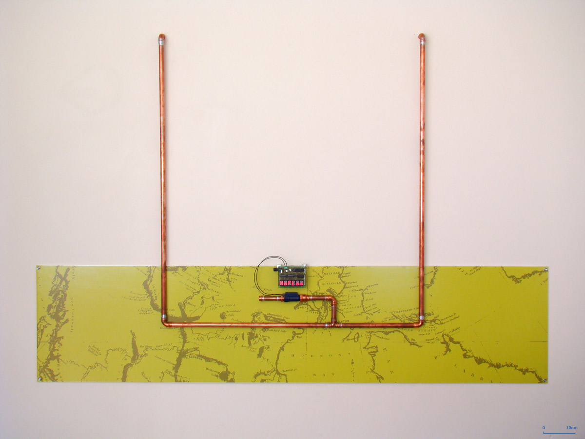
The Technology of Good Intentions”, “Northwest Passage” is an exploration of the difficulties and risks inherent in development and discovery. In the case of this piece, the end result is a water flow display. When there is no water flowing through the copper pipe, the display reads “noFlow”. When water flows, the display will read “Flow”. However, as experience has taught us, we can often get bogged down in solving a project’s many small technical details and fail to resolve one major one. In this case, while the software and computer hardware have been thoroughly tested, the fatal flaw is in the placement of the sensor: it is positioned out of the way of the water flow. As a result of this error, the display will always read “noFlow”. The title of the piece is a reference to the Franklin Expedition of 1845, which was lost in its search for the “northwest passage” from Europe to the Orient. The ships became trapped in ice and all perished.

The flow sensor is a simple switch which closes when an adequate flow of fluid passes through the device. The switch is connected to an Arduino ATMEGA8 microcontroller, which interprets the signal from the switch to change the reading on three two-element NFD-5421 14-element alphanumeric LED displays. The Arduino passes the data to the LED displays via one 74LS139 Dual One-of -four Decoder/Demultiplexer, and two 74HC164 8-bit Serial to Parallel Shift Registers. The Arduino code for this project can be found here under a Creative Commons Attribution-Noncommerical-Share Alike 2.5 Canada License. Parts for the electronics were sourced from futurelec.com and seeedstudio.com. The circuit schematic sketch is at the bottom of this post.

The electronic unit can be powered with four AA cells, which are hidden in a case behind the circuit board. If they are nickel metal hydride batteries, you can expect to get about 27 hours before the voltage drops below 4.5 volts. The battery performance curves, comparing two common NiMH types, can be viewed at the bottom of this post.

The ATMEGA8 is running at only 8 MHz, so it works very hard to keep up with the needs of the display shift registers; this results in a slight display flicker.

The most expensive component of this piece is the graphic, which is a high-quality inkjet print on semigloss paper and laminated to foamcore. It measures 175cm wide by 38cm high (69 x 15 inches).

As an aside, it is this project that I used to demonstrate my prototyping technique at instructables.com.