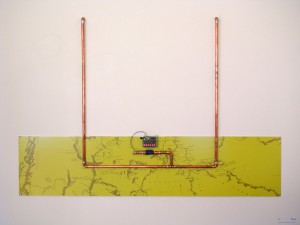
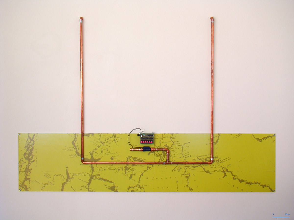
 As the first completed piece in the series “The Technology of Good Intentions”, “Northwest Passage” is an exploration of the difficulties and risks inherent in development and discovery. In the case of this piece, the end result is a water flow display. When there is no water flowing through the copper pipe, the display reads “noFlow”. When water flows, the display will read “Flow”. However, as experience has taught us, we can often get bogged down in solving a project’s many small technical details and fail to resolve one major one. In this case, while the software and computer hardware have been thoroughly tested, the fatal flaw is in the placement of the sensor: it is positioned out of the way of the water flow. As a result of this error, the display will always read “noFlow”. The title of the piece is a reference to the Franklin Expedition of 1845, which was lost in its search for the “northwest passage” from Europe to the Orient. The ships became trapped in ice and all perished.
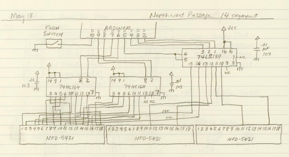
The flow sensor is a simple switch which closes when an adequate flow of fluid passes through the device. The switch is connected to an Arduino ATMEGA8 microcontroller, which interprets the signal from the switch to change the reading on three two-element NFD-5421 14-element alphanumeric LED displays. The Arduino passes the data to the LED displays via one 74LS139 Dual One-of -four Decoder/Demultiplexer, and two 74HC164 8-bit Serial to Parallel Shift Registers. The Arduino code for this project can be found here under a Creative Commons Attribution-Noncommerical-Share Alike 2.5 Canada License. Parts for the electronics were sourced from futurelec.com and seeedstudio.com. The circuit schematic sketch is at the bottom of this post.
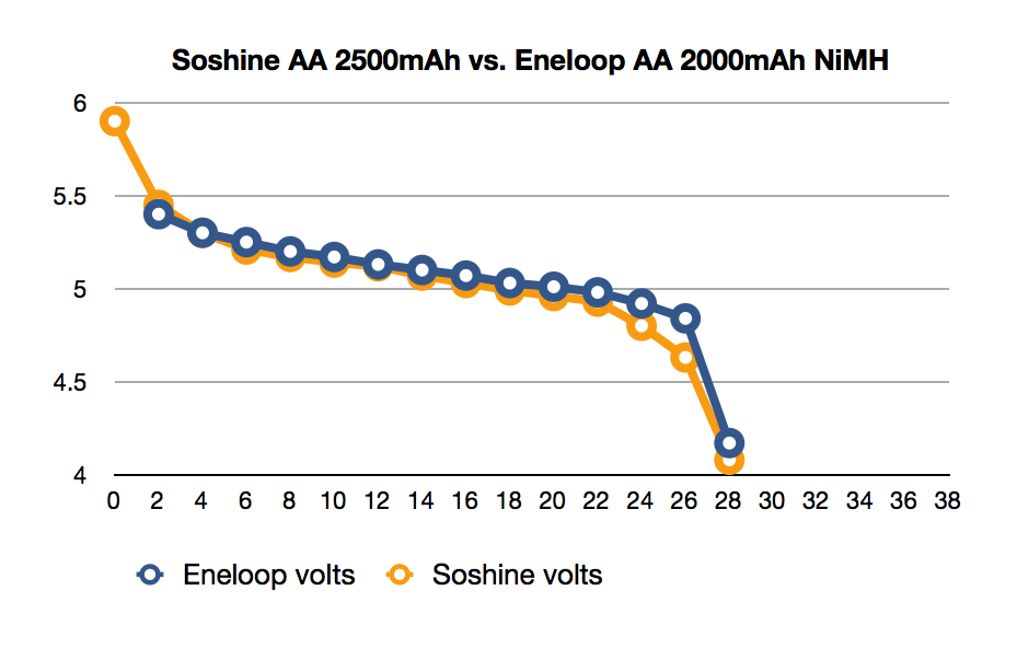
The electronic unit can be powered with four AA cells, which are hidden in a case behind the circuit board. If they are nickel metal hydride batteries, you can expect to get about 27 hours before the voltage drops below 4.5 volts. The battery performance curves, comparing two common NiMH types, can be viewed at the bottom of this post.
The ATMEGA8 is running at only 8 MHz, so it works very hard to keep up with the needs of the display shift registers; this results in a slight display flicker.
The most expensive component of this piece is the graphic, which is a high-quality inkjet print on semigloss paper and laminated to foamcore. It measures 175cm wide by 38cm high (69 x 15 inches).
As an aside, it is this project that I used to demonstrate my prototyping technique at instructables.com.
Northwest Passage by Michael B LeBlanc is licensed under a Creative Commons Attribution-Noncommercial-Share Alike 2.5 Canada License.
Contact the writer for permissions beyond the scope of this license.