Tag Archives: radio

Building Radios

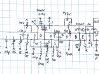
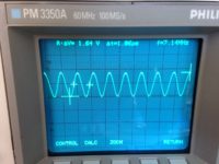
W1FB’s design for a VFO (Variable Frequency Oscillator): output on scope

I’ve not been posting consistently lately. The main reason is that I’ve been indulging my curiosity in radio technology. It started when I wanted to learn more about the wireless systems that I was building into my Arduino projects. The explorations and experimentation into radio have taken over, but I’ve not been able to answer in my own mind where this was taking me, until now.

So I’ve been building and playing with radio-frequency (RF) circuits, starting with oscillators, moving on to amplifiers and then simple radio receivers.

Some history might be helpful: A hundred years ago, when radio was new, experimenters built their own radio gear. The first radio transmitter was a device that made a spark, and a little later, sparks—which splashed energy promiscuously across a wide spectrum of frequencies—were replaced by narrow-frequency signals that could coexist with other signals with a radio that could select (or tune) into one signal and ignore the others. This signal is produced by an oscillator, which vibrates at a frequency of several million times a second.
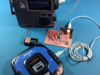
Low power AM transmitter for test purposes

Wireless signals—whether they be wifi, Bluetooth, FM or your garage door opener—all use oscillators to carry information. So step one in anyone’s search for knowledge in this field is to build an oscillator.

Actually, there’s a step zero: in Canada, the electromagnetic spectrum is considered public property. You just can’t set up a transmitter and spew electric energy in all directions. You need to abide by a set of regulations set by Innovation, Science and Economic Development Canada, and above a certain power level for your transmitter, you may need to obtain a licence. In my case, I have a Basic with Honours amateur radio license VE1LEB, which allows me to experimentally transmit, using commercially-designed equipment, up to 250 watts in certain high-frequency bands. Unless I upgrade my licence to “Advanced”, I’m not allowed to employ a transmitter that I build myself — unless it’s a kit and/or I’m transmitting at a very low level.
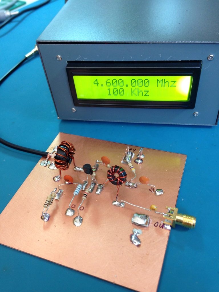
Used as a buffer for AD9851 frequency generator

So when I build experimental oscillators, I’m only allowed to run them at very low power so that they can’t be heard more than a few metres from my house.

Here’s a practical example from last summer: I wanted to test the performance of a radio that receives signals in the AM broadcast band, between roughly 500-1600 MHz, but in Halifax, Nova Scotia, all of the AM broadcasters have vacated this band in favour of the FM band. So when you turn on an AM radio in Halifax (during the day, at least), you’ll get noise, hiss, static, but nothing intelligible to a human. So I had to build my own little radio station that would modulate an audio signal from a CD player with a carrier wave around 1000 KHz. Tune the radio to around 1000, and you should hear music (but only if the radio is sitting next to the modulator circuit).

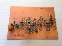
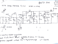
Here’s another example from last Fall: this circuit is from a design by Doug DeMaw W1FB that combines an oscillator with an amplifier. It’s a VFO (variable frequency oscillator) with a buffer amplifier that can be used as a stage in either a transmitter or receiver. The circuit was built on a single-sided PC Board, with islands of copper cut out using a copper engraver’s burin—a tool acquired during my days as a Fine Art Major. The components are soldered onto the islands. The rest of the copper is known as a ‘groundplane’: reserved for connection to zero volts (ground).
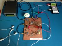
Direct conversion receiver

After that, with an increase in confidence, I moved on to building simple radio receivers. The first one used an amplifier design from the book “Crystal Sets to Sideband” by Frank Harris K0IYE. It’s known as a direct conversion receiver, one that’s unusual from most radios we use today because it doesn’t make use of intermediate frequencies to step the signal down from it’s original frequency to audio frequency. The radio is composed of an oscillator an RF board and an AF amplifier.
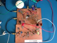
Direct conversion receiver – close up

The radio signal is brought into the receiver via a coax cable gold connector at the top left. This signal is mixed with a sine wave signal at almost the same frequency as the one we want to tune to. By varying the frequency of the oscillator, we can tune into different frequencies, which will be displayed on the frequency generator unit. When these two signals are combined, the difference frequency is the audio from the radio station. This low-level audio is transferred to the lower board with a short coax cable to the audio amplifier, which drives small earbuds for listening. The battery pack at the top right delivers about 12 volts to the radio.

This report gets me caught up to late October 2016. My next post will introduce “regens“. I realize that I haven’t revealed where all this activity is taking me in my design research. It will come in later posts.

73!
Wireless Home Monitor System

Over the past five years or so, I’ve been tinkering with wireless monitoring in my home. One of my first projects in 2010 was the Remote Fuel Oil Gauge that used the OnShine RX/TX pair at 433 MHz.

Shortly after this, I began to explore home environmental sensing, using a new internet service called Pachube (then Cosm, now Xively). I built an internet-linked environmental sensor that’s now installed in my office at NSCAD.

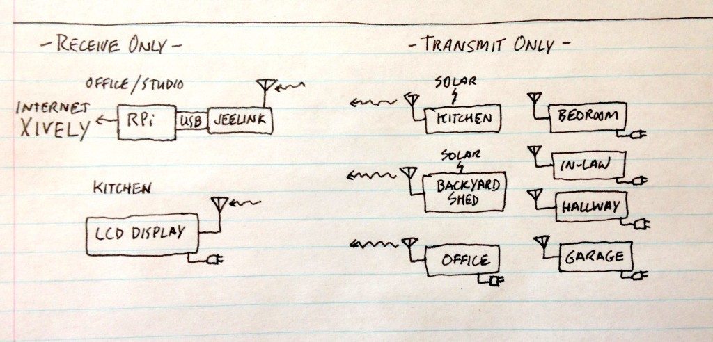
Next step was to build sensors that could wirelessly send data to a base station that would relay it to a central repository on the internet. To do this, I used Jean-Claude Whippler’s JeeNode library that enables the Hope RF12 and RF12B to communicate with each other and a base station JeeLink that can connect directly to a Raspberry Pi using its built-in USB.

Home Sensor Configuration

The basic configuration is comprised of the RPi and Python control and communication software that accepts the data from the JeeLink, does some conversions, and then sends it along to Xively. Xively handles the graphing.

Sensor Units

  • Basic Temperature only unit using DS1820
  • Basic Temperature and Humidity unit using DHT22
  • Garage unit: one DHT22 for garage, another DHT22 for “worm box”—Dorothea gives food scraps to worms, which process the scraps to good soil for the garden—plus a carbon monoxide sensor and a garage door open sensor
  • Office unit: one DHT22 plus a PIR sensor to detect activity in the office
  • Kitchen sensor unit: one DHT22. Solar powered.
  • Backyard Shed sensor unit: one DHT22. Solar powered.

Display Unit

There’s one LCD display on the kitchen refrigerator door that displays data from the Garage unit; if the garage door is open, a redLED blinks at .5 Hz.

More on various aspects of the system… later.

Military Room Escape Movie Prop

Well, hello there. It was a long, dreadful, record-breaking winter here in Nova Scotia. Although most of the snow has melted, it’s still unseasonably cold. I heard on local radio today that people are calling it “springter”. My last post was in October, and since then I’ve been occupied with teaching, promoting NSCAD programs in China and chairing an academic department; things that are either not blog-worthy or worth repeating publicly.

Weather Sensing Invention

Around the time of my last post, I had stumbled upon what I think might be a new invention relating to weather sensing. With the help of Kevin Buchan, NSCAD’s research consultant, I issued a proposal to Innovacorp for an Early Stage Commercialization Fund grant to help develop a working prototype. I heard at the end of February that I didn’t get the grant, so that’s off the table for the moment. By the way, my friend and colleague Sol Nagler received funding for his “Narratives – A Geolocative Interactive Storytelling Mobile Application” project. At least, I thought he was my friend. 😉

Radio

Over the past number of years, I’ve been utilizing tiny RFM12 and RFM12B 434 MHz radio units to send and receive sensor data around the house. These units use Arduino ATMEGA 328 microcontrollers and the Jeenode Library. I hope to talk more about this long-term project in future posts.

The more I worked with these magical devices, the more interested I became in their inner workings. Specifically, I wanted to know:

  • how to get the RF energy from the little circuit out to the world
  • what kinds of environmental factors affect the propagation of the RF energy
  • how to maximize and direct the RF energy from the sensor to a base receiver

However, in my research I was confronted with a wall of my own ignorance; as I searched for answers, more questions kept popping up. So I decided to undertake a long-term study, and as part of that plan I applied for my amateur radio license. I took the test on March 31 and received my Basic with Honours license, which allows me to use all of the HF, VHF and above amateur radio bands using standard commercially-designed and built radios. I want to be able to design and build my own transmitters, but that will have to wait until I can pass the Advanced license test. My callsign is VE1LEB. The VE1 prefix indicates my location as Nova Scotia, Canada.

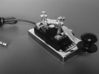
Changshu K-4 Heavy Key

So what’s the “Military Room Escape Movie Prop”? It comes from the AliExpress listing for a Chinese Army Changshu K-4 morse code key that I received in the mail yesterday. These keys have been in service in the Chinese military from the early 1960’s. It weighs one kilogram and it’s a thing of beauty! Morse code hasn’t been a requirement for amateur radio licensing in Canada for ten years, but I’m learning to send and receive anyway and hope to take the 5 wpm test in the Fall to get this function added to my certification.

So until next time, 73!