 My previous post on this subject dealt with the fuel oil level sender unit which sits atop the fuel oil tank in the garage. It has a look only its creator could love. On the other hand, the receiver unit needs to reside in the kitchen, so it has to be, at worst, presentable, and at best, a work of art.
The result is something in-between.
I wanted my receiver box to have an art deco-retro look, something like this or this. Most commercially-available project boxes are utilitarian in design. They lack the curves and finish of early 20th century North American manufactured goods (to say the least), so I designed my own.
I was constrained by lack of access to a complete range of wood- and metal-working machinery, so compromises had to be made. I decided to build the box out of medium density fibreboard, sandwiching together several layers to build depth. MDF is relatively easy to work, although it’s not a good idea to breathe in the dust.
One other aspect of the look relates to my fascination as a child with gas stations and large signs. I remember visiting my grandparents in Wakefield, MA in the middle of the summer; late at night I could part the sheer curtains in the second floor bedroom and look through the trees at a large neon “Pegasus” Mobil Oil gas station sign. I remember being rather disappointed several years later, not being able to see the sign and realizing that it had been replaced by a more modern fluorescent sign that didn’t blink on and off. So I wanted to have the pegasus represented somewhere in my design.
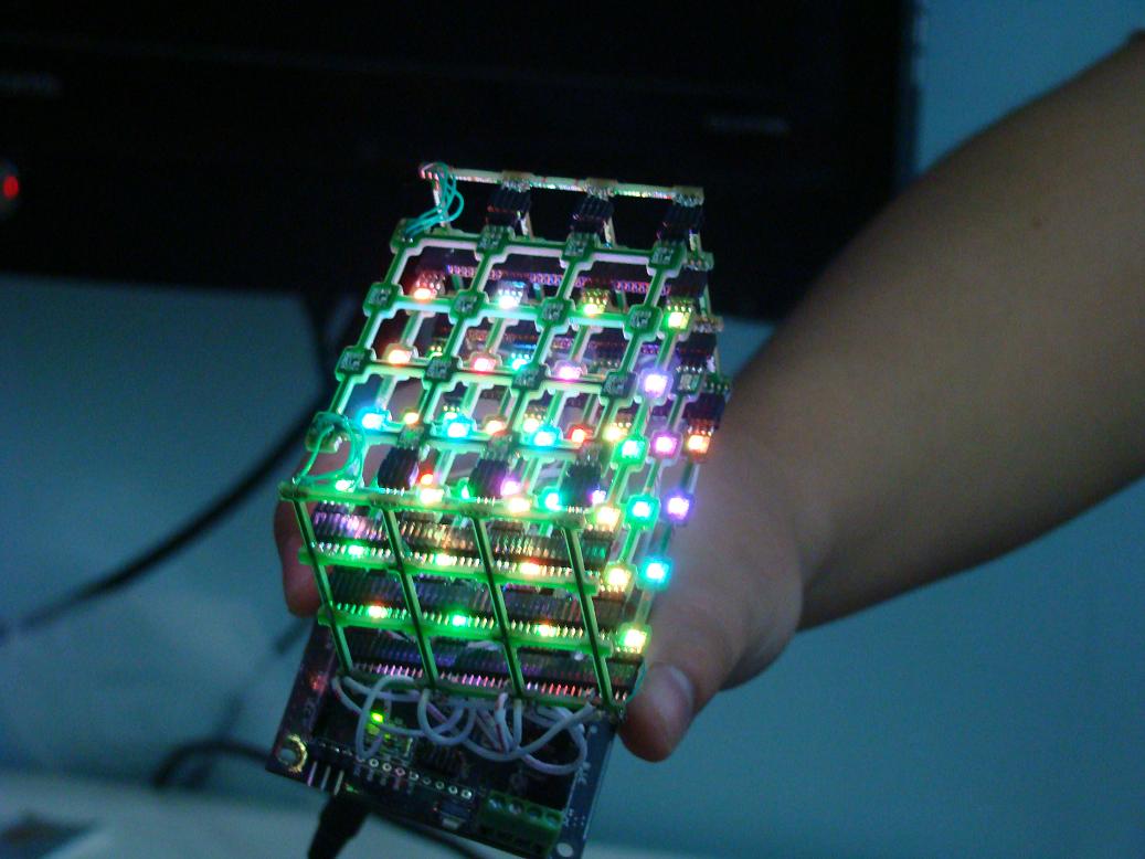
 My design uses 5 layers of MDF, with thicknesses ranging from 1/8″ to 1/2″. The different layers needed to be cut differently to accommodate the electronics, which included the SMCC-547 stepper motor and an Arduino controller.
When I designed the box, I used Cinema4D to work out how the parts would all fit together in 3D. I also used Adobe Illustrator to work out the measurements. Once I had the plan I gave it to my son Daniel, a NSCAD sculpture major, to cut the MDF and clear acrylic. Unfortunately there was a misunderstanding regarding dimensions. I won’t go there, except to say that even NASA has made this mistake.
It took some time to mitigate the effects of the misunderstanding, but in the end the result is satisfactory.
Electronics Hardware: The Receiver

The receiver has an Arduino brain and uses an On Shine RX A27 receiver (the pair of the transmitter in the sender unit). The received code is received by a Holtek HT12D decoder which passes along three bits of data to D6-D8 of the Arduino chip. My original design used an Arduino Mini Pro, but instead I installed the Arduino bootloader onto a virgin ATMEGA8 chip and set the fuses to run with the internal oscillator at 8 MHz. This was a much more economical choice than using the Mini Pro: $5 versus $30. The Mini Pro runs at 16 MHz and has 16kb of program storage while my minimal ATMEGA8 runs at around 8 MHz and has barely 7kb of program storage, but since I did not need the speed and the firmware fit easily into the 7k space, the ATMEGA8 was completely adequate.

The Arduino receives the 3-bit information from the decoder and uses D10-D13 to drive the SMCC-547 stepper motor module. In addition, the Arduino’s D2 pin is configured as an input from an hall effect position sensor: at power-up, the initialization routine in the software rotates the pointer counter clockwise. The pointer has a tiny magnet on its underside and when it approaches the sensor which is mounted on the motor, the rotation stops, effectively ‘zeroing-out’ and initializing the pointer position.
The Software
The actual work is accomplished by two routines: rotateRight() and rotateLeft(): The level of the oil tank is expressed as a three-bit binary number (binary 000-111 or decimal 0-7). The current level is compared to the previous level. If the current level is higher than the previous one, rotateRight() is invoked, which moves the pointer higher. If the current level is lower than the previous one, rotateLeft() is invoked which moves the pointer down.
A function called getLevel() converts the binary coded data into decimal.
As mentioned above, on power-up, the last state of the pointer is unknown, so the pointer is set to the zero point on the gauge. Once this is done, the main loop can commence.
/*
Stepper Motor SMCC-547 for Oil Tank Level Indicator v. 1.0

 by Michael LeBlanc
 NSCAD University
 mleblanc@nscad.ca

 It receives a binary value from 0 - 7 and moves the pointer
 accordingly.

 March 30, 2010
 */

/*
**************** N O T E **************************************
 This unit does not work with the stepper.h library.
 It works by setting one pin high and the others low.
 To rotate clockwise, set inputs high in order A-B-C-D,
 and D-C-B-A rotates counterclockwise.
 ***************************************************************
 */

int activePin = 1; // which of the 4 pins to the motor is high
int outputPin[5] = {
 0,10,11,12,13};  // stepper motor pins
int level;  // the current level of the oil tank
int oldLevel; // the previous reading of the level
int motordelay = 10; //standard stepper motor delay

void setup()
{
 pinMode(10, OUTPUT); // to A input on motor
 pinMode(11, OUTPUT); // to B input on motor
 pinMode(12, OUTPUT); // to C input on motor
 pinMode(13, OUTPUT); // to D input on motor
 pinMode(6, INPUT); // 1's digit of oil level
 pinMode(7, INPUT); // 2's digit of oil level
 pinMode(8, INPUT); // 4's digit of oil level
 pinMode(9, INPUT); // 8's digit of oil level (not required)
 pinMode(2, INPUT); // position sensor

 // step the pointer two to the right
 rotateRight();
 delay(motordelay);
 rotateRight();
 delay(motordelay);
}

void rotateLeft()  // rotate counterclockwise routine
{
 if (activePin == 4)
 {
 activePin = 1;
 digitalWrite(outputPin[4], LOW);
 digitalWrite(outputPin[1], HIGH);
 }
 else
 {
 digitalWrite(outputPin[activePin], LOW);
 activePin = activePin + 1;
 digitalWrite(outputPin[activePin], HIGH);
 }
}

void rotateRight()   // rotate clockwise routine
{
 if (activePin == 1)
 {
 activePin = 4;
 digitalWrite(outputPin[1], LOW);
 digitalWrite(outputPin[4], HIGH);
 }
 else
 {
 digitalWrite(outputPin[activePin], LOW);
 activePin = activePin - 1;
 digitalWrite(outputPin[activePin], HIGH);
 }
} // end rotateRight routine

int getLevel()
{
 int L0 = digitalRead(6); // read 1's digit of level
 int L1 = (digitalRead(7)*2); // read 2's digit of level
 int L2 = (digitalRead(8)*4); // read 4's digit of level
 level = ( L0 + L1 + L2 ); // convert to decimal
}

void loop()
{
 // initialization routine to set pointer to zero //

 if (digitalRead(2) == LOW)
 {
 //digitalWrite(3, LOW); // for debugging
 while (digitalRead(2) == LOW)
 {
 rotateLeft();
 delay(motordelay);
 }
 //digitalWrite(3, HIGH); // for debugging
 }
 else
 // set the pointer to the level //
 {
 getLevel();
 for (int i=1; i<=level; i++)
 {
 rotateRight();
 delay(motordelay);
 }
 oldLevel = level; // set oldLevel to equal current level

 /*-----------------------------------------------
 now manage incremental changes up or down //
 --------------------------------------------*/

 for (int looop=0; ; looop++)  // endless loop
 {

 getLevel();
 //Serial.print("Old Level: ");
 //Serial.print(oldLevel);
 //Serial.print(" Level: ");
 //Serial.print(level);
 //Serial.println(" ");

 if (oldLevel == level) // if there is no change, do nothing
 {
 delay(motordelay);
 }
 else if (oldLevel > level) // if level goes down, rotate left
 {
 rotateLeft();
 //Serial.println("rotate left");
 oldLevel = oldLevel - 1;
 delay(motordelay);
 }
 else
 {
 rotateRight();  // level has gone up; rotate right
 //Serial.println("rotate right");
 oldLevel = oldLevel + 1;
 delay(motordelay);
 }
 }
 }
}
![]()
Remote Fuel Oil Tank Gauge by Michael B LeBlanc is licensed under a Creative Commons Attribution-Noncommercial-Share Alike 2.5 Canada License.
Contact the writer for permissions beyond the scope of this license.


