January 23, 2017
Using the circuit from Servo controlling circuit, I breadboarded this:
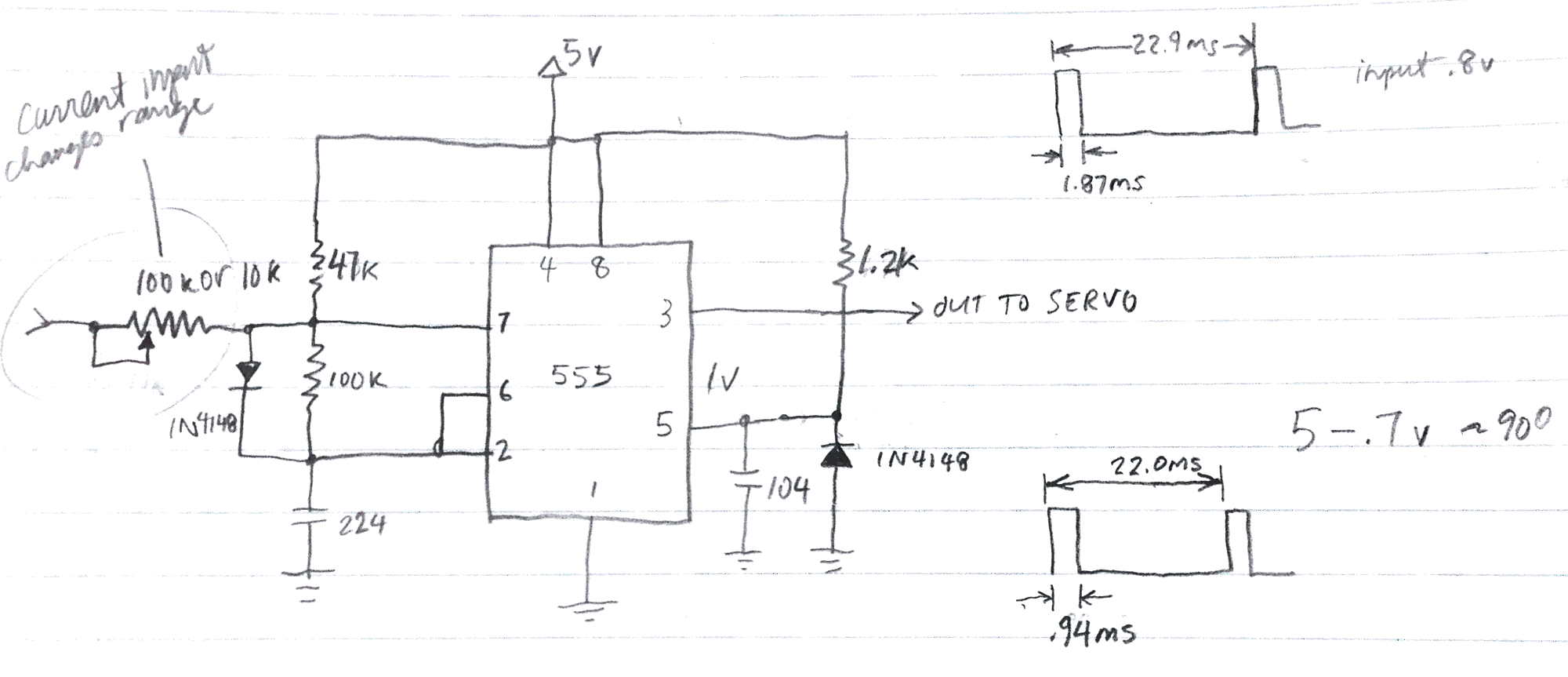
Results in a clean PWM pulse train, however:
- with pin 7 on the 555 biased to 1.47v, travel is less than 90 degrees between inputs of .7 and 5 v.
January 26, 2017
Adjusted circuit:
- the input current determines the rotational range of the servo, so we need to place a trimmer pot there
- waveform is clean and pulses are spaced at a consistent 22ms apart
January 27, 2017
- tested circuit on my WBR Regen 31m receiver: results are difficult to repeat with any consistency.
- circuit loading on radio changes calibration—this would make it difficult to use with different radios
- loading also affects tuning
- On the positive side, circuit continues to outperform op-amp and Arduino circuits, with no problems of power supply dropouts
Conclusion
I think that it’s time to go back to the Arduino-controlled circuit to see if I can wrangle the power-dropout-reset issue.