Fun with Regenerative Receivers

Hackaday recently had a post called “Everyone Should Build at Least One Regenerative Receiver“. These are relatively simple radios to build and they can receive any type of modulation, from AM to Single Sideband, to FM. Although the regen is one of the oldest receiver designs, it’s still widely used in garage door openers, walkie-talkies and wireless “internet of things” devices.

Over the past year or so, I’ve taken the “at least one” part of the title literally. Last year I built several regens, some successful, some not:

John Fuhring’s Regen Receiver – April–October 2016

John Fuhring has an extensive and entertaining account of his attempts at building a Charles Kitchin “Scout Beginner’s Receiver” regen kit. Because he was so forthcoming about his ups and downs in his regen saga, I decided that I’d try following in his footsteps for my first scratch-built regen.

My plan was to use a variation of the manhattan style of component placement, by cutting-out spaces from a grid of squares on the copper surface of the pc, as I did with the oscillator/amplifier project described in the previous post.

The radio tuned from 6.4 – 8.0 MHz. Although successful, it had poor selectivity (radio stations on top of each other), it had a hum from the power supply that was alleviated by substituting a battery, and the LM386 audio amplifier was susceptible to troublesome ‘motorboating’. I disassembled this radio in December 2016.


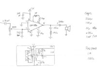
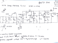
Ray Ring’s High Performance Regenerative Radio – October 2016

Tuning Devices compared
Tuning Devices compared. From left to right, an air variable capacitor, a polyvaricon, and a varactor.

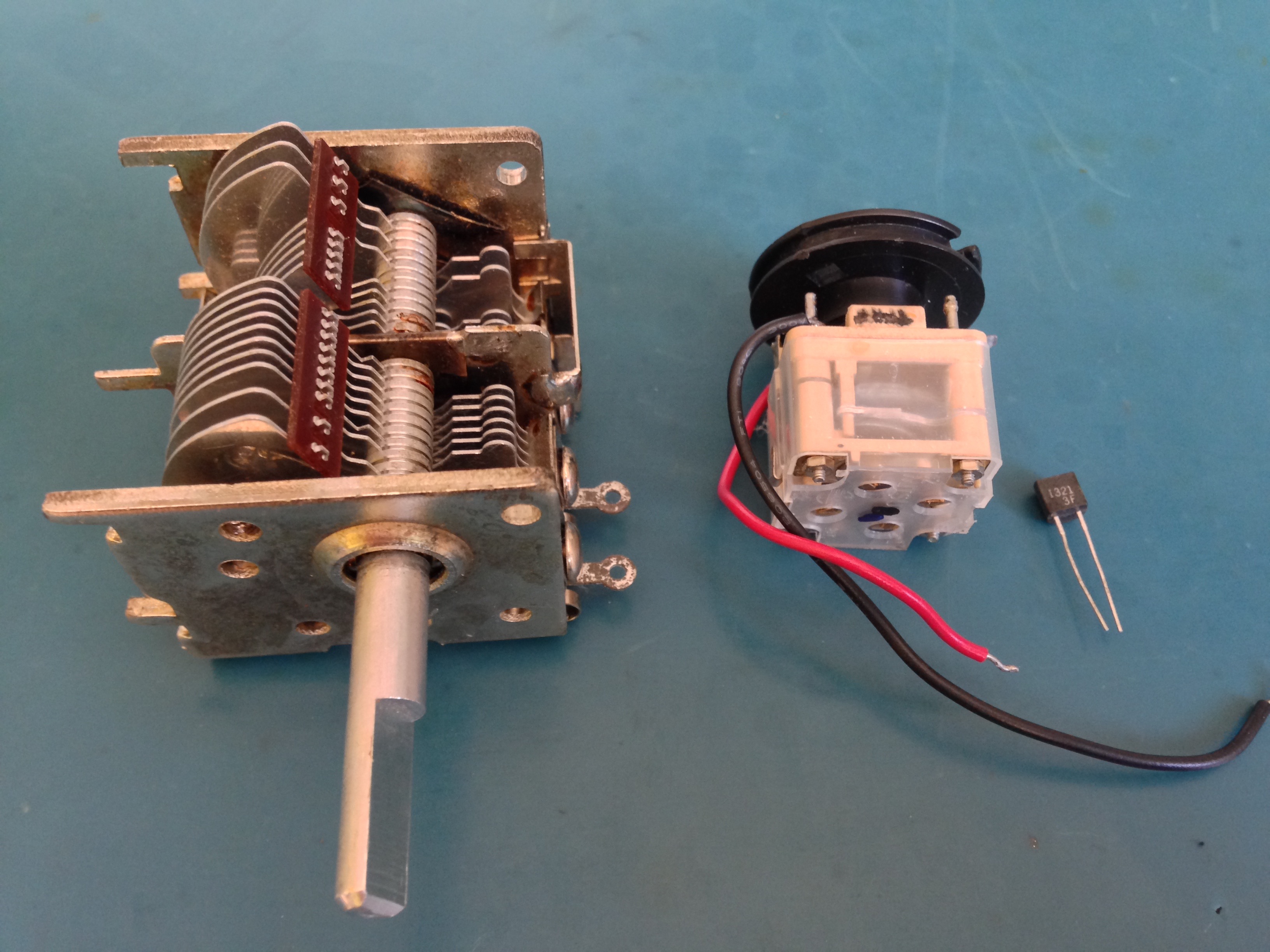
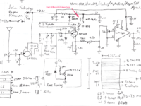
What attracted me to this circuit were the words “high performance” (although as I’ve discovered, a large percentage of designs promote themselves this way, but in my experience “high performance” may not fully apply) and the fact that the tuning mechanism can be easily adapted to employ a solid state “varactor” rather than the old-school and increasingly hard to find “air variable capacitor”. I’ve managed to collect a few air variables over the past couple of years. They have good selectivity but the dial travel is only about 180°, so they are difficult to tune unless you build a string pulley dial (used in most table radios back in the day) or use a vernier reduction gear mechanism (expensive and also hard to find).

Varactor performance graph
Some experimentation shows that the tuning is fairly linear from 5 – 8 volts.

There are two alternatives to the air variable: the first is the “polyvaricon”, which is used in most clock radios and portable transistor radios. It doesn’t have as good selectivity as an air variable, and it’s also difficult to tune. The other is the “varactor”: this is a special diode which changes its capacitance based on the amount of voltage that is used to bias it. A varactor is tuned with a potentiometer—standard pots have a travel of around 270°, which is better than variable capacitors—and you can also use an inexpensive ten turn pot which can tune into even the narrowest of signals.

RRing Regen Build
The low pass filter is at the top of the photo to the left of the speaker. Also on a separate board in the centre right is the LM386 audio amp circuit.

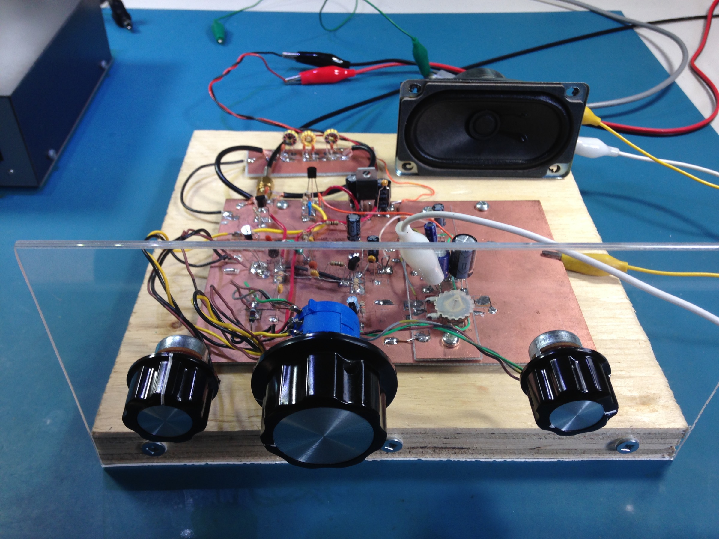
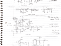
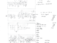
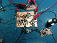
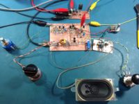
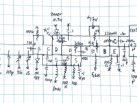
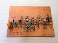
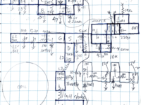
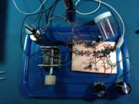
My initial build of Ring’s circuit used a polyvaricon, then two in parallel but the result was unstable. I tried different varactors. I also struggled with local FM broadcast interference: to combat the breakthrough, I built a 7-pole Butterworth low pass filter. I discovered that the hookup wire in the RF part of the radio was also picking up FM broadcast harmonics, so I replaced the wires to and from the low pass filter with RG174 coax, and that solved the problem. As you can see, I used the manhattan style construction technique.

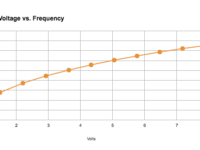
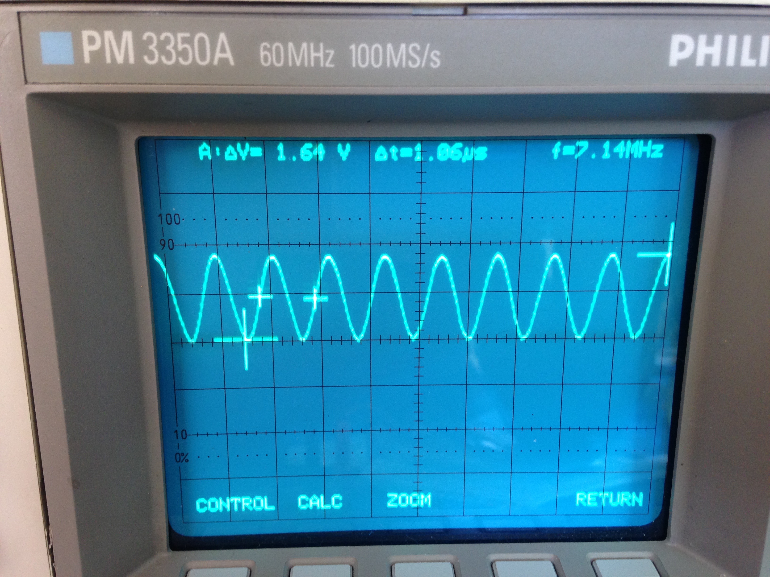
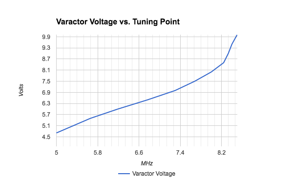
After much experimentation, I settled on a BB112 varactor which the data sheet says goes from 470pF at 1v down to 20pF at 8v. For reasons that I can’t remember, I set the voltage/tuning range of the radio from 4.75 – 8.5v, which gave me an effective tuning range at one point from 5.0 – 8.2 MHz. I then changed from a small commercial wirewound 11.5 µH inductor to a 5µH hand-wound T50-6 toroid inductor. The radio now tunes from 7.8 – 13.2 MHz.


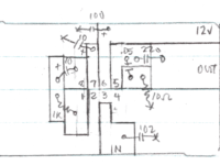
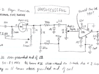
W1FB Doug DeMaw’s Two-stage Regen from his Design Notebook – Unsuccessful

From November 2016, an even simpler design: this one came from the “W1FB Design Notebook”, figure 5-2. The circuit uses a customary Armstrong tapped coil with one Field Effect Transistor (effectively replacing Armstrong’s original vacuum tube). For this build, I used the same technique as the John Fuhring regen above, rather than using copper islands/manhattan construction for the previous radio.

Unfortunately, I could not get the radio to oscillate. Looking back on it, there may have been several reasons for this:

  1. the coil was too close to the copper groundplane
  2. there may have been some solder resin remaining on the board; resin can conduct
  3. it’s possible that I got the windings of the coil backwards

WBR Regen Receivers

WBR receiver - AA7EE's design
WBR receiver – AA7EE’s design

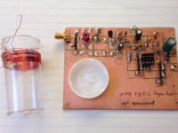
In late December, I built a wheatstone bridge regen using AA7EE’s circuit. Although it did work, performance was disappointing.

I disassembled it shortly thereafter.

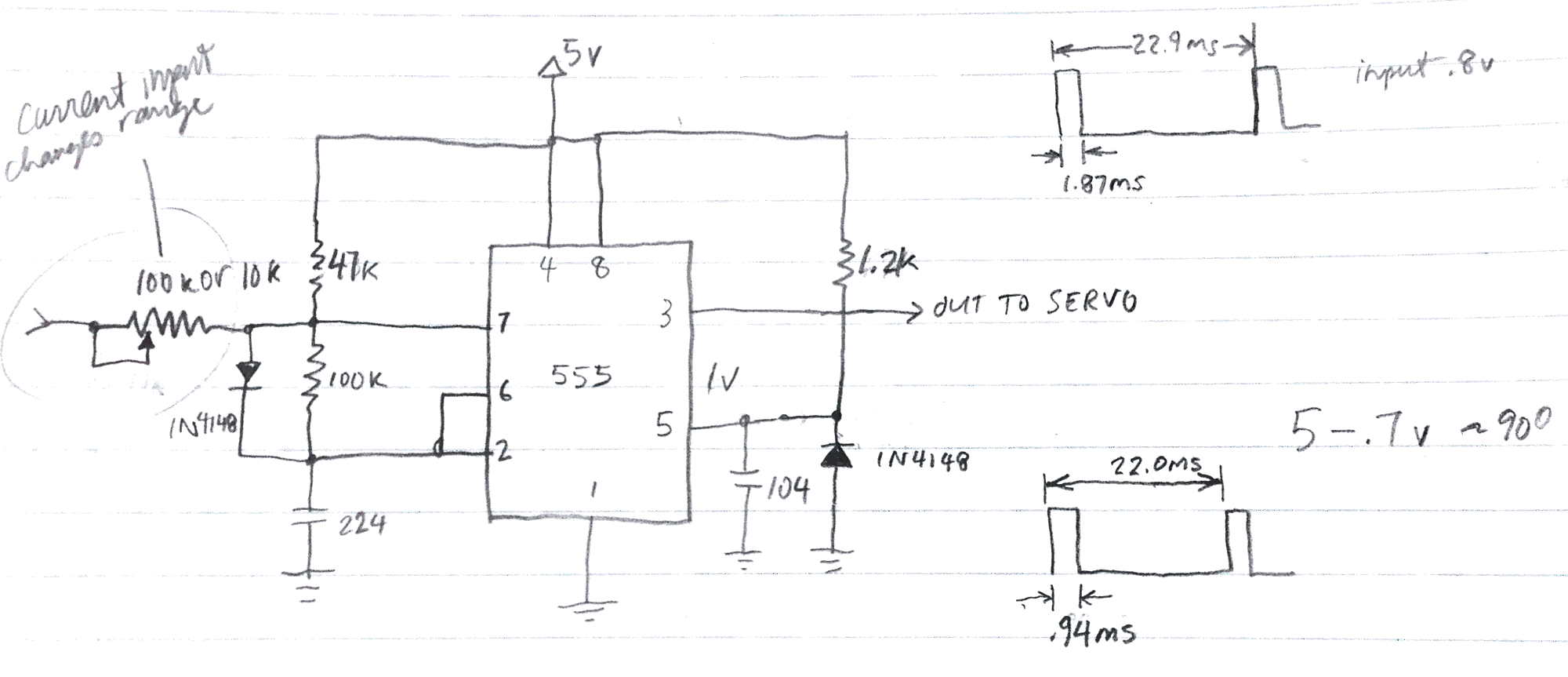
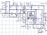
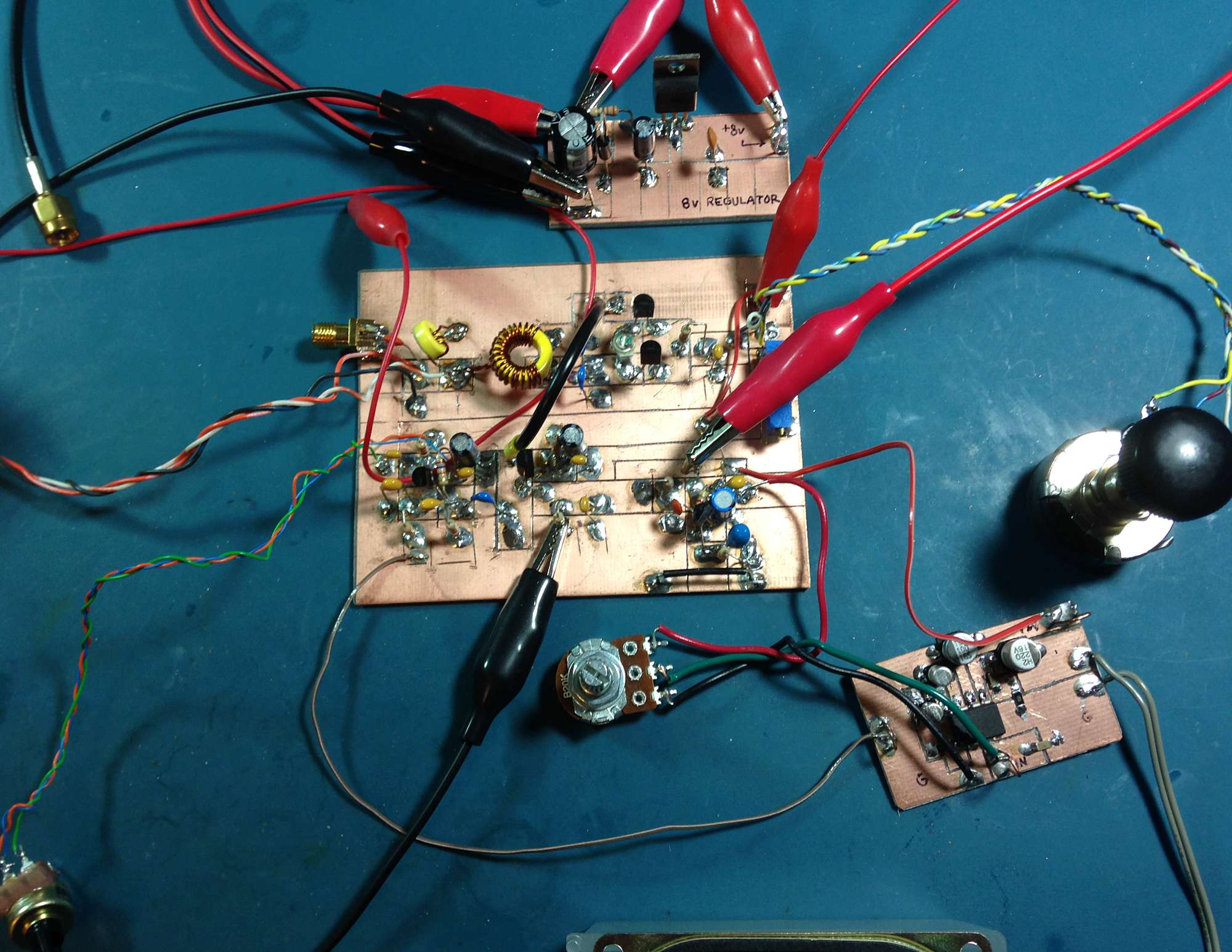
The WBR idea remained interesting to me. I found an article from QST August 2001 called “The WBR Receiver” by Dan Wissell, N1BYT. I used his design for my next radio. My notes:

Dec 28 2016
I had some difficulties building this. My first board was deaf—I think because I had mis-wired the connection from the final audio transistor to the LM386.
I made a new board and moved all the components over. The second board was milled using the Dremel stand with a milling table.
The second board, with two 10-turn pots (one for Regeneration and the other for Tuning) seems to work well, and tunes from 8.845 – 9.770 MHz.
Dec 29
  • the pot turn shafts are slightly wider than the knobs that I have. I experimented by using a cutting disk to cut a slot down the middle. Heats the pot up, but seems to do no lasting damage. Also tried just grinding down around the circumference, which seems a better solution.
  • took one turn off each end of the main inductor.
  • the trimpot controlling the lower tuning voltage limit was not wired in properly. Adjusted to bottom out around 1 volt.
  • radio now tunes from 9.450 – 10.070 MHz. Have not yet heard WWV.
Dec 31
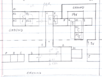
  • completed breadboarding: mounted boards and pots, replaced connecting wires with coax where desirable
  • reception seems stronger: however, AM and SSB signals seem to have a tremolo
  • radio now tunes from 9.410 – 10.010 MHz. Have heard WWV!

Jan 3, 2017

AN IDEA: replace the 8v regulator with a 5v regulator, and add a servo motor/Arduino to indicate frequency via voltage level.

Building Radios

W1FB’s design for a VFO (Variable Frequency Oscillator): output on scope

I’ve not been posting consistently lately. The main reason is that I’ve been indulging my curiosity in radio technology. It started when I wanted to learn more about the wireless systems that I was building into my Arduino projects. The explorations and experimentation into radio have taken over, but I’ve not been able to answer in my own mind where this was taking me, until now.

So I’ve been building and playing with radio-frequency (RF) circuits, starting with oscillators, moving on to amplifiers and then simple radio receivers.

Some history might be helpful: A hundred years ago, when radio was new, experimenters built their own radio gear. The first radio transmitter was a device that made a spark, and a little later, sparks—which splashed energy promiscuously across a wide spectrum of frequencies—were replaced by narrow-frequency signals that could coexist with other signals with a radio that could select (or tune) into one signal and ignore the others. This signal is produced by an oscillator, which vibrates at a frequency of several million times a second.

Low power AM transmitter for test purposes

Wireless signals—whether they be wifi, Bluetooth, FM or your garage door opener—all use oscillators to carry information. So step one in anyone’s search for knowledge in this field is to build an oscillator.

Actually, there’s a step zero: in Canada, the electromagnetic spectrum is considered public property. You just can’t set up a transmitter and spew electric energy in all directions. You need to abide by a set of regulations set by Innovation, Science and Economic Development Canada, and above a certain power level for your transmitter, you may need to obtain a licence. In my case, I have a Basic with Honours amateur radio license VE1LEB, which allows me to experimentally transmit, using commercially-designed equipment, up to 250 watts in certain high-frequency bands. Unless I upgrade my licence to “Advanced”, I’m not allowed to employ a transmitter that I build myself — unless it’s a kit and/or I’m transmitting at a very low level.

Used as a buffer for AD9851 frequency generator

So when I build experimental oscillators, I’m only allowed to run them at very low power so that they can’t be heard more than a few metres from my house.

Here’s a practical example from last summer: I wanted to test the performance of a radio that receives signals in the AM broadcast band, between roughly 500-1600 MHz, but in Halifax, Nova Scotia, all of the AM broadcasters have vacated this band in favour of the FM band. So when you turn on an AM radio in Halifax (during the day, at least), you’ll get noise, hiss, static, but nothing intelligible to a human. So I had to build my own little radio station that would modulate an audio signal from a CD player with a carrier wave around 1000 KHz. Tune the radio to around 1000, and you should hear music (but only if the radio is sitting next to the modulator circuit).

Here’s another example from last Fall: this circuit is from a design by Doug DeMaw W1FB that combines an oscillator with an amplifier. It’s a VFO (variable frequency oscillator) with a buffer amplifier that can be used as a stage in either a transmitter or receiver. The circuit was built on a single-sided PC Board, with islands of copper cut out using a copper engraver’s burin—a tool acquired during my days as a Fine Art Major. The components are soldered onto the islands. The rest of the copper is known as a ‘groundplane’: reserved for connection to zero volts (ground).

Direct conversion receiver

After that, with an increase in confidence, I moved on to building simple radio receivers. The first one used an amplifier design from the book “Crystal Sets to Sideband” by Frank Harris K0IYE. It’s known as a direct conversion receiver, one that’s unusual from most radios we use today because it doesn’t make use of intermediate frequencies to step the signal down from it’s original frequency to audio frequency. The radio is composed of an oscillator an RF board and an AF amplifier.

Direct conversion receiver – close up

The radio signal is brought into the receiver via a coax cable gold connector at the top left. This signal is mixed with a sine wave signal at almost the same frequency as the one we want to tune to. By varying the frequency of the oscillator, we can tune into different frequencies, which will be displayed on the frequency generator unit. When these two signals are combined, the difference frequency is the audio from the radio station. This low-level audio is transferred to the lower board with a short coax cable to the audio amplifier, which drives small earbuds for listening. The battery pack at the top right delivers about 12 volts to the radio.

This report gets me caught up to late October 2016. My next post will introduce “regens“. I realize that I haven’t revealed where all this activity is taking me in my design research. It will come in later posts.

73!

More Experiments in Servo-actuated Frequency Displays

January 23, 2017

Using the circuit from Servo controlling circuit, I breadboarded this:
555 servo control using variable voltage
Results in a clean PWM pulse train, however:
  • with pin 7 on the 555 biased to 1.47v, travel is less than 90 degrees between inputs of .7  and 5 v.

January 26, 2017

Adjusted circuit:
  • the input current determines the rotational range of the servo, so we need to place a trimmer pot there
  • waveform is clean and pulses are spaced at a consistent 22ms apart

January 27, 2017

  • tested circuit on my WBR Regen 31m receiver: results are difficult to repeat with any consistency.
  • circuit loading on radio changes calibration—this would make it difficult to use with different radios
  • loading also affects tuning
  • On the positive side, circuit continues to outperform op-amp and Arduino circuits, with no problems of power supply dropouts

Conclusion

I think that it’s time to go back to the Arduino-controlled circuit to see if I can wrangle the power-dropout-reset issue.