Tag Archives: Arduino

Parking Assistant

Using an Arduino, a simple three-wire ultrasonic rangefinder, and an RGB distance indicator, you can park your car with precision.

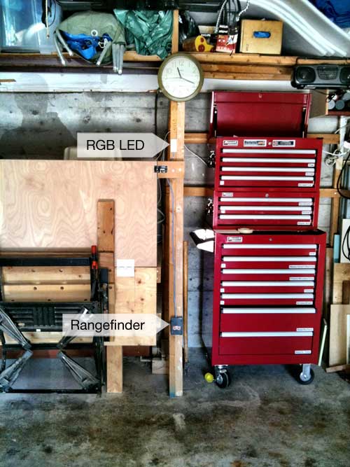
Contrary to most people I know who have garages, we still use ours to store our car. And when we did a minor garage renovation—actually, it was more of a cleanup and reorganization—I decided to build a gadget that would give us an indication of how close we are to the back (inside) wall of the garage.

There are many devices available for drivers to help them gauge their car’s position. My brother Ralph has a simple low-tech solution: hang a tennis ball from the ceiling. Works great as long as you always enter the garage leading with the front of the car. Other solutions include a laser, a stopper on the floor, a photo-electric beam, and an ultrasonic rangefinder from GE—Not General Eccentric. Those other guys.

The GE device is battery-operated and uses a red/yellow blinking LED for driver feedback. This device can be configured to display red at a distance of 1, 2, or 3 feet from the rangefinder.

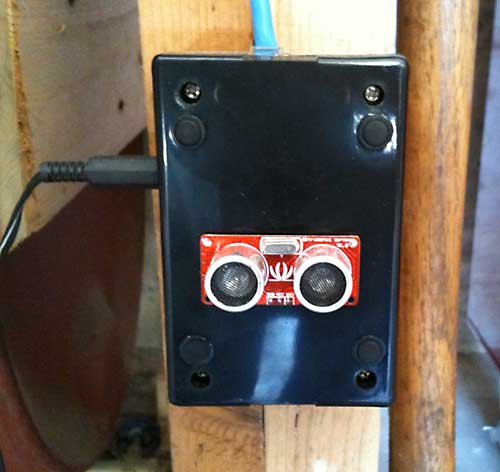
My device operates using a wall transformer (actually, I’m using spare capacity from the transformer that powers my Oil Tank Level Sender project) and employs a non-blinking RGB LED that glows green until the car bumper reaches 30 inches distance to the rangefinder, orange from 30 inches to 12 inches, red from 12 inches to 6 inches, and blue/purple 6 inches or less.

Download Electronic schematic (pdf).

Here’s the sketch, which is adapted from the David Mellis/Tom Igoe “Ping Sensor” example that comes with the current Arduino IDE:

/* Ping))) Sensor

   This sketch reads a PING))) ultrasonic rangefinder and returns the
   distance to the closest object in range. To do this, it sends a pulse
   to the sensor to initiate a reading, then listens for a pulse
   to return.  The length of the returning pulse is proportional to
   the distance of the object from the sensor.

   The circuit:
	* +V connection of the PING))) attached to +5V
	* GND connection of the PING))) attached to ground
	* SIG connection of the PING))) attached to digital pin 7

   http://www.arduino.cc/en/Tutorial/Ping

   created 3 Nov 2008
   by David A. Mellis
   modified 30 Jun 2009
   by Tom Igoe

   This example code is in the public domain.

 */

// this constant won't change.  It's the pin number
// of the sensor's output:
const int pingPin = 7;
const int redPin = 6;
const int greenPin = 5;
const int bluePin = 4;

void setup() {
  // initialize serial communication:
  //Serial.begin(9600);
  pinMode (redPin, OUTPUT);
  pinMode (greenPin, OUTPUT);
  pinMode (bluePin, OUTPUT);
}

void loop()
{
  // establish variables for duration of the ping,
  // and the distance result in inches and centimeters:
  long duration, inches;

  // The PING))) is triggered by a HIGH pulse of 2 or more microseconds.
  // Give a short LOW pulse beforehand to ensure a clean HIGH pulse:
  pinMode(pingPin, OUTPUT);
  digitalWrite(pingPin, LOW);
  delayMicroseconds(2);
  digitalWrite(pingPin, HIGH);
  delayMicroseconds(15);
  digitalWrite(pingPin, LOW);
  delayMicroseconds(20);
  // The same pin is used to read the signal from the PING))): a HIGH
  // pulse whose duration is the time (in microseconds) from the sending
  // of the ping to the reception of its echo off of an object.
  pinMode(pingPin, INPUT);
  duration = pulseIn(pingPin, HIGH);

  // convert the time into a distance
  inches = microsecondsToInches(duration);

  if (inches > 30) {
    digitalWrite(greenPin, HIGH);  // green LED
    digitalWrite(redPin, LOW);
    digitalWrite(bluePin, LOW);
  }
  else if (inches <= 30 && inches > 12) {
    digitalWrite(greenPin, HIGH);
    digitalWrite(redPin, HIGH);    // orange LED
    digitalWrite(bluePin, LOW);
  }
  else if (inches <= 12 && inches > 6) {
    digitalWrite(redPin, HIGH);    // red LED
    digitalWrite(greenPin, LOW);
    digitalWrite(bluePin, LOW);
  }
  else {
    digitalWrite(redPin, HIGH);    // purple LED
    digitalWrite(greenPin, LOW);
    digitalWrite(bluePin, HIGH);
  }

  delay(100);
}

long microsecondsToInches(long microseconds)
{
  // According to Parallax's datasheet for the PING))), there are
  // 73.746 microseconds per inch (i.e. sound travels at 1130 feet per
  // second).  This gives the distance travelled by the ping, outbound
  // and return, so we divide by 2 to get the distance of the obstacle.
  // See: http://www.parallax.com/dl/docs/prod/acc/28015-PING-v1.3.pdf
  return microseconds / 74 / 2;
}

Introducing Media Circus

Media Circus is a scrolling marquee that displays amusing headline news mashups.

Although this project is not quite finished, it’s at a point where I can show it: what’s missing is the ability of the unit to automatically update the headlines (once every hour). Currently, this appliance needs to be manually updated.

Cutup

Media Circus Concept Drawing

Media Circus is composed of several modules, starting with “Cutup”, a mashup generator which is a php script that retrieves rss headlines from two Canadian news services, recombines them and displays 20 of them in HTML format. This isn’t by any means a new concept: it’s actually an old dadaist party game. William Burroughs used cutups in his writing. Visit Publicassemblage, runme.org, and Cut-up Machine for more online examples of this technique.

From this list, a human operator chooses one or two and makes minor edits to prepare them for inclusion in the unit. For the time being, I’m the ‘human operator’, and my choices are regularly uploaded to the ‘generalxcentric’ Twitter feed. I use Hootsuite to schedule the tweets throughout the day.

I’ll be building Cutups for the USA and the UK, and in the more distant future, provide a Media Circus mobile app that will enable users to generate their own news headline mashups!

The Hardware

The marquee runs on an Arduino Duemilanove (ATMEGA328 microcontroller). Power is supplied by an LM317T adjustable voltage regulator configured to output 5v. The regulator delivers up to 1.5 amps current, more than enough to drive the four SURE 0832 displays, but you must attach a heatsink—the regulator gets very hot.

I specify the ATMEGA328 because it has 2k of internal SRAM memory, and in the case of this application, it’s important. This microprocessor has three types of random access memory:

  • 32k Flash memory, of which about 2k is used by the Arduino bootloader.
  • 2k SRAM (Static ram), which is used to hold variables created by the program at runtime
  • 1k EEPROM memory, available using the PROGMEM function

The Flash memory is the same technology used in USB thumb drives. It is relatively slow to write to and reasonably fast to read from. It’s non-volatile, which means that it doesn’t lose data if power is removed. The 2k SRAM (Static Random Access Memory) is used for temporary storage of variables. It’s fast with both reading and writing, but it’s volatile. The EEPROM (Electrically-erasable Programmable Read-Only Memory) is also volatile, and it is very slow to write to, and fast to read from. The Arduino IDE does not have a function to make use of this memory. If you need it, you have to load the avr/prgmspace.h library and invoke PROGMEM.

For the purposes of this application, I quickly ran into the 2k SRAM limit, for two reasons:

  1. Each headline uses about 70 characters, which means that if I want ten headlines, I need to reserve 700 bytes (30%) of my available 2000 bytes of SRAM. That’s just to create the variables. Then my program had to concatenate the headlines into a long string of characters to be displayed by the marquee sign. That’s about ¾ of my available SRAM. I solved the problem by moving the individual headlines directly into EEPROM space at program startup, freeing-up 700 bytes.
  2. What actually drives the marquee is Gaurav Marek’s brilliant HT1632 library for Arduino. Along with this library comes a 5×4 font file. As you may have guessed from the name of the font file, each letter uses a rectangle of maximum 4 pixels across and 5 pixels down. However, the SURE 0832 display has a height of 8 pixels, so I redesigned the font for larger letters. The disadvantage to the new font file is size: my new font uses about 20% more space in SRAM than the original.

These SRAM space challenges were surmounted in time by moving the individual headlines into PROGMEM, and limiting the number of headlines displayed to seven.

However the SRAM requirements were not settled, because my plan was to attach an Ethernet Shield to the Arduino. The shield has its own library (conveniently included in the Arduino IDE), which requires more SRAM. But when I attached the shield, the unit failed to run. I tried reducing the headlines to one that simply read “help” but the marquee remained blank. There’s probably some interaction between the HT1632 library and the ethernet library, but I’m not competent or patient enough to try to resolve that issue.

I had another Ethernet shield, this one from Nuelectronics. This shield uses a different chip and has different libraries, and is altogether a more challenging device to integrate into an Arduino sketch. Although the shield does work with the marquee sketch, I was unable to adapt the library examples to my uses. That will have to wait for later.

SURE 0832 Display

The 0832 comes with ribbon cables and dip switches, prepared to be linked to three other modules. It’s a fairly simple matter to connect one module to the next and at the left end of the array, this is where you connect the Arduino. This is the pinout chart for my system, which uses Guarav Maurek’s HT1632 library. It permits easy individual pin assignments—a very useful utility, since Ethernet shields often use particular pins that can’t easily be changed. The pins on the SURE modules are labeled clearly on the back of each board.

Source Files

Click here for a ZIP archive of the Media Circus Arduino sketch and modified ‘font_5x4.h’ file for larger dot matrix type.

Update September 4, 2011

You can view more photos from this project at General Eccentric.

Update April 19, 2013

The General Eccentric Book and updated final code and drawings are available here.

Clock with Tics (using SURE 0832)

Clock with Tics using Sure Electronics 0832

When I posted the original prototype of the Clock with Tics, Arduino Forum member mowcius commented that all the wiring and matrix driving could be greatly simplified with the LED matrices from Sure Electronics. While I was aware of the Nanjing-based company, I had not bought anything from them, nor had I seen them in the several electronics supermarkets that I had stumbled upon when I last visited the city.

Long story short: I bought a yellow LED 0832 module on ebay from Sure: they are remarkably cheap, about $9 each. Four of them can be strung together to make a respectable scrolling-message sign. Single units can be easily driven by an Arduino Duemilanove, but you can also buy a driver board that handles the higher current requirements if you need to string several together.

When I received it, I was busy with other matters and I put it aside. When I had a few hours here and there, I pulled it out and tried making the connection with an Arduino. I was not successful in getting past the self-test mode.

Last weekend, while waiting for replacement parts to arrive (also from Sure Electronics, by the way) for my ‘Shy Dildo’ project, I thought I’d attack the problem one last time. I had earlier unsuccessfully scoured the net for references to the 0832 module, but this time, I looked for “HT-1632”, which is the Holtek driver chip that’s used in the Sure module. Bingo!

I found several Arduino libraries that purport to work with HT1632 units. The first one that I successfully connected was from MakeHackVoid; it demonstrated the pin connections between the 0832 and the Arduino, and linked to libraries that enabled the 0832 to do the ‘crawling words’ scrolling thing. I spent most of the weekend playing with the code and re-working the somewhat erratic-looking font that came supplied with it. I could not, however, simply write a static string to the 0832.

Then I found Miles Burton’s library. This library has good documentation, and made it possible for me, a dopey artist, to figure out how to adapt the ‘Clock with Tics’ code from the presentation prototype to the Sure 0832 matrix. The process of getting to this point was complicated by several factors:

  1. A bad connection in a breadboard hookup wire
  2. Difficulties in sorting out the five different libraries that I had experimented with during the course of three days.
  3. A poor understanding (on my part) of the nature of chars and strings. I was unable to get my head around these concepts, and why the C language makes translation between chars and strings (and among other formats) so complicated. The Arduino String Library has limited documentation, and there doesn’t seem to be much in the way of helpful information elsewhere online. I don’t have any formal training in computer programming, and until Arduino I had avoided C.

The circuit for the new model should fit comfortably on one 6x9cm circuit board. I estimate that it is about 90% simpler to assemble. It has an added feature of a CDS (light cell) that allows the display to fade or brighten depending on the ambient light.

Clock with Tics for SURE Source Code (Github)

Clock with Tics for SURE Schematic (PDF)